RUGGEDCOM RX1100
Installation Guide
Chapter 1
Introduction
Ports, Controls and Indicator LEDs
3
Section 1.2
Ports, Controls and Indicator LEDs
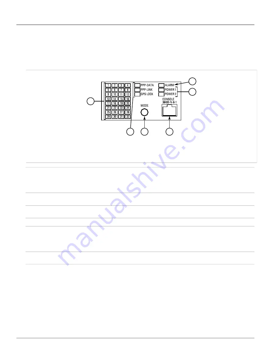
The RX1100 features various ports, controls and indicator LEDs on the front panel for configuring and
troubleshooting the device.
5
1
3
6
4
2
Figure 1: Front Panel
1.
Port Status Indicator LEDs
2.
Display Mode Indicator LEDs
3.
Mode Button
4.
Alarm Indicator LED
5.
Power Module Indicator
LEDs
6.
RS232 Serial Console Port (RJ45)
Port Status Indicator LEDs
These LEDs indicate the state of each port.
• Green (Solid) = Link detected
• Green (Blinking) = Link activity
• Off = No link detected
Display Mode Indicator LEDs
These LEDs indicate the current display mode for the port status indicator LEDs (i.e. PPP-
DATA, PPP-LINK or GPS LOCK).
Mode button
The
Mode
button sets the display mode for the port status indicator LEDs (i.e. PPP-DATA,
PPP-LINK or GPS LOCK). It can also be used to reset the device if held for 5 seconds.
Alarm Indicator LED
The alarm indicator LED illuminates when an alarm condition exists.
Power Module Indicator LEDs
These LEDs indicate the status of the power modules.
• Green = The power supply is supplying power
• Red = Power supply failure
• Off = No power supply is installed
RS232 Serial Console Port
This port is for interfacing directly with the device and accessing initial management
functions.


