RUGGEDCOM RSG2100PF
Installation Guide
Chapter 2
Installing Device
Connecting External PoE Power
15
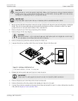
6. Install the supplied metal jumper between terminals 2, 4 and 6 to connect the surge ground terminals to
the chassis ground terminal. The surge ground terminals are used as the ground conductor for all surge and
transient suppression circuitry internal to the unit.
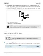
7. Using a #6 ring lug and #6-32 screw, secure the ground terminal on the power source to the chassis ground
terminal on the device. Make sure the lug is tightened to 1.7 N·m (15 lbf·in).
2
1
3
Figure 7: Chassis Ground Connection
1.
Stainless Steel Stud
2.
#6-32 Screw
3.
#6 Ring Lug
DANGER!
Electrocution hazard – risk of death, serious personal injury and/or damage to the device. Make
sure the supplied terminal block cover is always installed before the device is powered.
8. Install the terminal block cover.
Section 2.5.2
Connecting External PoE Power
The RUGGEDCOM RSG2100PF supports up to four 10/100Base-TX Power-over-Ethernet (POE) Ports that require
power from an external source.
NOTE
For IEC 61850 compliance, use an IEC 61850 compliant PoE power supply with power cabling no
longer than 3 m (118 in).
External Power Supply Requirements
To support the
IEEE 802.3af
specification (15 W/port output), the external power supply must meet the following
requirements:
Input Range
Power Supply Type
Minimum
Maximum
Isolation
Minimum
Power Required
DC
45 VDC
57 VDC
1.5 kVAC/2.2 kVDC
75 W

