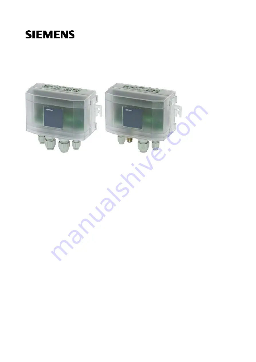
Modbus air pressure sensor with I/O extension
QBM97..
User Guide
A6V11478123_en_a
Building Technologies
2019-02-01
Page 1: ...Modbus air pressure sensor with I O extension QBM97 User Guide A6V11478123_en_a Building Technologies 2019 02 01 ...
Page 2: ...s 7 1 4 Wiring 8 1 4 1 Electrical grounding 8 1 4 2 Power supply 9 1 4 3 Signal wiring 10 2 Commissioning 12 2 1 Addressing 12 2 1 1 DIP switches Climatix and other controllers 12 2 1 2 On event addressing Climatix controllers 13 2 1 3 Baud rate 13 2 2 Fault detection correction or reset 14 3 Engineering 15 3 1 Implementing volume flow measurement 15 3 2 Modbus registers 16 4 Maintenance 20 4 1 Ze...
Page 3: ...peration of the device system described here requires proper transportation correct warehousing mounting installation commissioning operation and maintenance You must comply with permissible ambient conditions You must comply with the information provided in the Section Technical data and any notes in the associated documentation Fuses switches wiring and grounding must comply with local safety re...
Page 4: ...Mount the sensor in a location that is easy to open the cover and access the terminals DIP switches and view the LEDs Proceed as follows to mount the sensor to a surface Screw the sensor at the 2 brackets on the device sides to the mounting surface Keep the following guidelines All measurements in millimeters 134 5 5 min 75 q ...
Page 5: ...9 02 01 1 1 1 Dimensions QBM97 all dimensions in mm Front view QBM97 here without M12 Side view QBM97 here without M12 Bottom view QBM97 opened cover AQB9120 101A and AQB9220 101A 81 9 45 35 5 5 5 146 134 60 42 33 11 3 9 10 151 4 175 56 70 28 4 6 3 4 16 6 5 60 78 5 16 100 40 6 1 4 ...
Page 6: ...and detached cover 1 6 22 Siemens A6V11478123_en_a Building Technologies 2019 02 01 1 2 Quick release fasteners and detached cover Open the housing with the quick release fasteners The cover can easily be detached completely 1 1 2 90 2 2 1 ...
Page 7: ...Installation Connecting tubes 1 7 22 Siemens A6V11478123_en_a Building Technologies 2019 02 01 1 3 Connecting tubes Connect the tubes Avoid loops ...
Page 8: ...The reference of RS485 transceiver is connected to GND all GND pins are on the same potential if the Climatix controller and QBM97 are connected to the same power source take care to avoid miswiring between 24 V input and GND The document Modbus communication J3960 provides profound information on Modbus grounding Transformer Power supply 24V 0V REF B A Earth Sensor module Not isolated RS485 M Sit...
Page 9: ...Installation Wiring 1 9 22 Siemens A6V11478123_en_a Building Technologies 2019 02 01 1 4 2 Power supply Terminal 24V 24V Diagram Note Earth is optional 24V 24V ...
Page 10: ...lustrate all signal types of a QBM97 1 4 3 1 Analog inputs Analog inputs for passive sensors Use Connecting passive temperature sensors Signal types Pt1000 LG Ni1000 NTC10k and Ni1000 Terminal AI1 AI2 Diagram Analog inputs for voltage signal Use Connecting devices that supply a 0 10 V signal Terminal AI1 AI2 Diagram AI1 AI2 AI1 AI2 ...
Page 11: ... 11 22 Siemens A6V11478123_en_a Building Technologies 2019 02 01 1 4 3 2 Analog outputs Analog outputs with voltage signal Use Connecting devices that are controlled with a 0 10 V signal Terminal AO1 AO2 Diagram M M AO1 AO2 ...
Page 12: ... is valid as soon as all DIP switches are on 0 Changes of DIP switches are effective after 5 seconds Modbus addressing The DIP switches allow addresses between 1 247 Modbus specification The following example shows Modbus address 3 Modbus termination The termination is done with 120 Ω 1nF Even if the addressing is done with On event addressing Climatix controllers 13 the termination has to be done...
Page 13: ...econds 2 As soon the button is released the status LED lights up orange The QBM97 receives temporarily address 246 so that a communication can be established Automatic baud rate recognition is done Format changes to 1 8 E 1 Master writes the Modbus parameters Master writes 1 into register 4x0768 Bus config command 3 QBM97 gets its final Modbus address by the application HMI Further settings are ma...
Page 14: ...eliability analog inputs register 4x0008 4x0010 0 no error no error no error 1 no sensor disruption in operation sensor not connected 2 overload overload temperature 150ºC 3 underload negative pressure temperature 50ºC 4 open loop 5 short time overload short time overload 6 no output signal 7 other error zero point reset required 8 calculation error 9 extended error 10 EEPROM protection active 11 ...
Page 15: ...ic k factor of the measured device into register 4x0083 sensor 1 and or 4x0093 sensor 2 Permitted range 0 1500 2 Select requested unit in register 4x0084 sensor 1 and or 4x0094 sensor 2 Selectable are m3 h m3 s or l s QBM97 calculates the flow value 3 Read out the flow value from registers 4x0081 4x0082 flow low flow high of sensor 1 resp registers 4x0091 4x0092 flow low flow high of sensor 2 The ...
Page 16: ... 1250Pa 1 x 2500Pa 9717 1 x 1250Pa 1 x 7000Pa 9722 2 x 2500Pa 9777 2 x 7000Pa uint16_t 4x0002 Error Code 1 R uint16_t 4x0003 Analog output coupling 1 R W 0 analog output coupled with differential pressure sensors default 1 analog output coupled as defined in 4x0028 4x0058 setpoint uint16_t 4x0004 Differential pressure 1 Reliability 1 R uint16_t 4x0005 Differential pressure 1 Value see config R uin...
Page 17: ... 1 R W 0 VAL Scaling high 0 default uint16_t 4x0030 Scaling high 10 0V mV 1 R W Scaling low VAL 10000 default uint16_t Differential pressure 1 Addr Description Unit Scaling R W Range Data type 4x0035 Reliability 1 R uint16_t 4x0036 Value 1 R uint16_t 4x0037 Unit 1 R W 0 Pa default 1 PSI 2 mmHG 3 mmH2O uint16_t 4x0038 Value Pa Pa 1 R uint16_t 4x0039 Value PSI PSI 0 0001 R uint16_t 4x0040 Zero point...
Page 18: ... 1 R W 0 VAL Scaling high 0 default uint16_t 4x0060 Scaling high 10V mV 1 R W Scaling low VAL 10000 default uint16_t Differential pressure 2 Addr Description Unit Scaling R W Range Data type 4x0065 Reliability 1 R uint16_t 4x0066 Value 1 R uint16_t 4x0067 Unit 1 R W 0 Pa default 1 PSI 2 mmHG 3 mmH2O uint16_t 4x0068 Value Pa Pa 1 R uint16_t 4x0069 Value PSI PSI 0 0001 R uint16_t 4x0070 Zero point c...
Page 19: ...91 Flow low 0 01 R uint16_t 4x0092 Flow high 0 01 R uint16_t 4x0093 k factor 1 R W 0 VAL 1500 uint16_t 4x0094 Unit 1 R W 0 m3 h default 1 m3 s 2 l s uint16_t Modbus Settings according to Climatix Addr Description Unit Scaling R W Range Data type 4x0764 Modbus address 1 R W 1 VAL 247 255 default uint16_t 4x0765 Baudrate 1 R W 0 auto default 1 9600 2 19200 3 38400 4 57600 uint16_t 4x0766 Format 1 R ...
Page 20: ...s again NOTICE Use cases of the zero reset As the allowed mounting position is vertical only see Mounting 4 the sensor does not have to be recalibrated during commissioning in the case of normal pressure measurement Only in case of relative pressure measurement pressure nipple connected to ambient atmosphere a zero point calibration is recommended during commissioning 10 20 s Blue ...
Page 21: ...sions and Modbus registers A6V11478118 User guide Modbus air pressure sensor with I O extension QBM97 Installation commissioning engineering maintenance and Modbus registers A6V11478123 Integration guide Modbus communication Modbus networks electrical and grounding information plus commissioning workflow J3960 Basic documentation Climatix AHU application Complete description of the Climatix AHU ap...
Page 22: ...on International Headquarters Theilerstrasse 1a CH 6300 Zug 41 58 724 2424 www siemens com buildingtechnologies Siemens Switzerland Ltd 2019 Technical specifications and availability subject to change without notice Document ID A6V11478123_en_a Edition 2019 02 01 ...