background image

60 / 143

Siemens

Web Server OZW672... V6.0

CE1C5712en

Building Technologies

Operate using a web browser

2015-10-13

4.4  File 

transfer

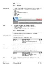
"File transfer" helps to

·

  Create and manage Trend functions

·

  Upload documents to the Web Server.

·

  Download message history as Excel or text file.

·

  Upload logos.

·

  Upload system definitions.

Creating and managing Trend functions is described in Section 8 "Trend functions".

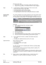
Procedure:
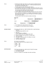
1.  Select File transfer in primary navigation.
2.  Select documents in secondary navigation
3.  Click [ Add ]

4.  Click [Browse] and select desired file.
5.  The upload starts directly after selecting the desired files and clicking [Open].

·

  Make sure there is enough memory for uploading.

·

  The Administrator and Service levels allow for uploading documents.

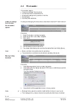
Procedure:
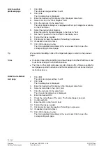
1.  Select Message history from secondary navigation.
2. Click

 next to the desired document. TXT for text or ASCII format and XLS

for Excel-Format.
The "File download" dialog box opens.

3.  Open the file with the application or save it to any location.

·

  Message history export is available to administrator and service user levels.

·

  The message history remains intact when resetting the Web Server to default.

Create and manage
Trend function

Documentation
Upload

Notes

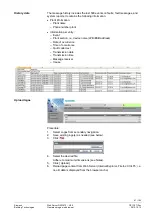
Message history
download

Notes

Summary of Contents for OZW672.01

Page 1: ...s LPB and BSB plants Web Server OZW672 V6 0 Commissioning instructions OZW672 01 OZW672 04 OZW672 16 CE1C5712en 2015 10 13 Building Technologies ...

Page 2: ...lding Technologies 2015 10 13 Siemens Switzerland Ltd Building Technologies Division International Headquarters Gubelstrasse 22 6301 Zug Switzerland Tel 41 41 724 24 24 www siemens com buildingtechnologies Siemens Switzerland Ltd 2010 Subject to change ...

Page 3: ... of day date 25 2 5 3 Operating page Faults current 26 2 5 4 Operating page Settings 26 2 5 5 Operating page Device information 36 2 6 Commission network components 37 2 6 1 Access via portal 37 2 6 2 Access via home network LAN 37 2 6 3 Access via direct connection 38 2 7 Functional check 40 2 8 Additional settings 42 2 9 Final steps 43 2 9 1 Check faults 43 2 9 2 Final steps on Web Server 43 2 1...

Page 4: ...ibility 81 6 2 6 Summary display Energy indicator for a plant 82 6 3 Energy indicator commissioning function 83 6 3 1 Commissioning notes 83 6 3 2 Start Energy indicator function 83 6 3 3 Estimated processing time 84 6 3 4 Deactivating Data point monitoring 84 6 3 5 Activating Data point monitoring 86 6 4 Dialog boxes data points and Green limits 88 6 4 1 General dialog boxes 88 6 4 2 Dialog boxes...

Page 5: ...ontents and appendix 118 8 4 Download Trend file via web 119 8 5 Graphical trend display 121 8 6 Import export Trend definitions 122 8 7 ACS Trend 125 8 7 1 ACS offline Trend compatibility 125 8 7 2 ACS Trend bus load 126 9 Appendix 127 9 1 General notes 127 9 2 Diagnostics 127 9 2 1 Web Server fault codes 127 9 2 2 Windows commander 128 9 3 Communications 129 9 3 1 Internet protocol 129 9 3 2 Fre...

Page 6: ...6 143 Siemens Web Server OZW672 V6 0 CE1C5712en Building Technologies Table of contents 2015 10 13 ...

Page 7: ...f the user s guide can be downloaded at www siemens com ozw672 manual The ACS790 PC software can also be used to commission and operate the Web Server OZW672 To simplify reading this document focuses on commissioning and operating via web browser This symbol draws your attention to special safety notes and warnings Ignoring this type of note may result in device damage and personal injury Devices ...

Page 8: ...tallation and commissioning as intended as well as careful operation Dispose of the device as electronic waste in compliance with European directive 2002 96 EEC WEEE and not as municipal waste Observe all corresponding national legal regulations and dispose of the device via appropriate channels Comply with all locally applicable laws and regulations Intended use Disposal ...

Page 9: ...range LED 0 8 s on 0 2 s off Dark No bus power Lit LPB BSB operational Flashing Communication on LPB BSB No function Dark No fault normal operating state Lit Fault exists No function Long 6 s Sends system report to fault e mail recipients not to Energy indicator and Trend data recipients Long 6 s See Button combinations Long 6 s Simultaneously press and restores default factory settings Note All c...

Page 10: ...s Create device list and operating pages Device operation via home queries devices and their operating pages via secondary navigation menu tree The path displays the workflow starting at the main menu to the open operating page Simply click at any point on the path to return to that location This field shows the currently logged in user Clicking Logout ends the current session The session remains ...

Page 11: ...5712en Building Technologies Overview 2015 10 13 Displays plant name as entered The display range displays content corresponding to the selected function via primary and secondary navigation Shows Logo 1 and Logo 2 Plant name Display Logo area ...

Page 12: ...gged in user Operate end user data Fault overview Administer own user account The same as end user plus Operate service and end user data Trend functions Documents Message history Logos and System definitions The same as service plus Creation of device list and web pages Toolbar to create plant web pages Management of all user accounts End user Service Administrator ...

Page 13: ...tment tab Arrow to display sort order Up File upload to Web Server File download from Web Server Export file Import file Add data point Move sort data point Start Trend Stop Trend Generate graph Calendar to select date Safety note intended to protect against misuse Always observe follow Note important information Network connection Link to device User connected locally or via direct connection fix...

Page 14: ...nt Interface Crossed DHCP Dynamic Host Configuration Protocol DynDNS Dynamic Domain Name System HTTP Hyper Text Transfer Protocol HTTPS Hyper Text Transfer Protocol Secure IP Internet Protocol LPB Local Process Bus BSB Boiler System Bus NAT Network Address Translation PAT Port and Address Translation RNDIS Remote Network Driver Interface Specification STP Shielded Twisted Pair TCP Transmission Con...

Page 15: ... Web Server is fully commissioned The following is required to commission the Web Server on the portal The Web Server is connected to the Internet The Web Server automatically registers on the portal The operation LED starts to flash green orange as soon as the Web Server is connected to the portal The following is required to commission the Web Server A PC laptop and a web browser commission Web ...

Page 16: ...bus wiring and setting for the bus power supply on the bus device if no bus power supply is available LED Dark if no fault is pending You can resolve pending faults later see Section 2 9 3 Plug the supplied USB cable into the Web Server and the PC and start up the PC The PX recognizes the Web Server as a USB device Otherwise the RNDIS is still not installed 4 The RNDIS driver is installed automati...

Page 17: ...V5 2 Passwort Password Password as of V6 0 Password Password 1 4 Click Login to finish 5 After logging on the first time the dialog box is displayed to define a new password Web Server Sprache English A new password must be defined the first time you log in you can also change the language You cannot exit the dialog box if you do not define a new password i e not equal to Password resp Password 1 ...

Page 18: ...word strength is checked when entering the password and a progress bar displayed The bar is orange is the password is week It changes to green as soon as the password is strong enough The following conditions must be met for a secure password Minimum password length of 8 characters At least 1 capital letter At least 1 lowercase letter At least 1 number At least 1 special character Password and use...

Page 19: ... The user account settings equally apply to access via Smartphone app and other applications via Web API Procedure 1 Click red pencil symbol The Change user dialog box opens 2 Change administrator data Password Repeat Password Description optional Email address optional Language English 3 Click OK to finish Procedure 1 Click Add The Add user dialog box is displayed Administer user accounts Note Ch...

Page 20: ...scription optional E mail address optional Language English User group 3 Close with OK Procedure 1 Click red garbage can for the corresponding user The User accounts dialog box is displayed 2 Click Yes for User to be deleted The administrator account cannot be deleted The name Administrator and user group Administrator cannot be changed You may however add user accounts with administrator rights Y...

Page 21: ...ce list Only added bus devices are monitored Device web pages can only be generated on the Administrator user level Only generated bus devices can be operated Changes to settings of the connected bus device may require that the device web pages be recreated or updated to apply changes from web operation You must delete and re add a bus device after you update the bus device software or replace the...

Page 22: ...eb pages are generated The process may take a few minutes 9 Wait until Process finished is displayed In the device list the Web Server and the bus device display state Generated 10 The device websites are now available under Home Procedure 1 Select the bus device you want to remove from the device list 2 Click Delete 3 Click Yes to confirm The Web Server removes the device from the device list 4 W...

Page 23: ...anges to be applied you must recreate the device web pages after you update the system definition see Section 4 4 part Upload system definitions Device web pages can only be created on the Administrator user level Procedure 1 Select the devices whose web pages you want to newly create 2 Click Generate Device web pages are generated The process may take a few minutes 3 Wait until Process finished i...

Page 24: ... You must update the device web pages of the Web Server to apply all text changes to the menu You can update device web pages on user levels Administrator and Service Click Update on the Service and Generate on the Administrator level to start updating see Create device web pages The following update procedure applies to the Service level 1 Select the Web Server 2 Click Update The device web pages...

Page 25: ...3 Faults Fault inputs 1 2 Setting the fault inputs is described in Section 2 5 4 8 Inputs 2 5 2 Operating page Time of day date Path Home 0 5 OZW672 Time of day date The clock has a backup battery for at least 72 hours The clock continues to run after power failure for the duration of the backup battery Both date and time are reset in case of an extended interruption The time is corrected automati...

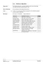
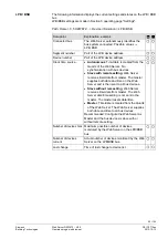
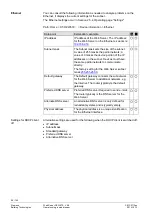
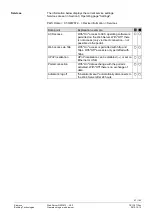
Page 26: ...erver fault text messages message history messages and system reports Code Default val 01 Setting val max 20 char Access code for PC Software ACS790 Reset admin password Default val No Setting val Yes If you do not know the administrator password for the Web Server setting value Yes again provides access to the Web Server via the administrator password Password Password Factory setting for adminis...

Page 27: ...g Slave without rem setting Master Autonomous Time date is created from the Quartz of the Web Server No synchronization with bus devices Slave with remote setting Web Server receives time date from master The master supplies both date and time on the Web Server and is then sent to all bus devices Slave without rem setting Web Server receives time date from master The Web Server date time setting i...

Page 28: ...ateway Default val 192 168 2 1 Setting val IP address The standard gateway represents the interface between the local and public network You typically enter the IP address for the router here Does not require setting if DHCP client On Preferred DNS server Default val 192 168 2 1 Setting val IP address The DNS server domain name system on the Internet connects a globally valid name to a domain with...

Page 29: ...sponds to the e mail address of the Web Server The email address is displayed in the From field of each email Authentification mail server Default val No Setting val No Yes Select Yes for mail server access with authentication In this case user name and password data points below are required User name Default val Blank Setting val Max 46 char User name and password help authenticate each e mail v...

Page 30: ...er registers its existence in the corresponding network using the Universal Plug and Play UPnP service Portal connection Default value On Setting values On Off On enables data exchange with the portal No data is exchanged under Off Automatic log off Default value On Setting values On Off The connection to Web Server automatically times out after 24 hours 2 5 4 4 Message receivers Data points are a...

Page 31: ... value is recipient email address The number of messages pending is available under Number of messages for sending A time frame can be defined during which messages can be sent for each receiver The following settings are optional when restricting the time for sending messages default settings No restriction In general Messages occurring outside the send periods are sent afterwards if still pendin...

Page 32: ... sending periods are defined via Send messages General Messages outside sending periods are resent during the next send period If a special day occurs during a holiday vacation the day is a special day Holidays special days can be set as recurring days each year Data point Explanation example Entry 1 16 Default val Setting val Beginning End Reason Annually Each recipient has a yearly calendar to e...

Page 33: ...tem report is to be sent the time can be defined Message cycle Default value 1 day Setting values 0 255 d resolution 1 day The setting value represents the distance in days for sending a system report The first system report is sent after the first message cycle expires and then the message cycle 0 switches of the system report Priority Default value Urgent Setting values Urgent Not urgent Filter ...

Page 34: ...ed interval to one or both e mail receivers Set at Path Home 0 5 OZW672 Settings Trend Descriptions are available in Section 8 3 Send Trend data by e mail 2 5 4 8 Inputs Path Home 0 5 OZW672 Settings Inputs Fault input 1 2 Digital inputs D1 D2 help connect potential free status contacts They act as fault inputs The following settings configure the fault inputs Response to faults is defined in menu...

Page 35: ...g A corresponding message is triggered at start and end of fault A Web Server fault displays the LED These data points can be set for fault input 1 and 2 Data point Explanation example Fault input 1 2 Default val Blank Setting val Max 20 char Customizable text for fault input The designation is displayed in the menu and transmitted as part of the message Identical to data point in Settings Inputs ...

Page 36: ...going A corresponding message is triggered at start and end of fault A Web Server fault displays the LED Message triggering System refers to faults from the bus device received via the LPB BSB bus 2 5 4 10 Texts Path Home 0 5 OZW672 Settings Texts Data point Explanation example Name Default val OZW672 01 OZW672 04 OZW672 16 Setting val max 20 characters User definable text for the plant displayed ...

Page 37: ... for the devices IP address Subnet mask Default gateway und Preferred DNS server are examples and show the various relationships dotted lines 2 6 1 Access via portal OZW registers automatically on the portal during commissioning as soon as it is connected to the Internet All functions are available after the user also logs on to the portal and the plant is activated No additional settings required...

Page 38: ...the plant via the Internet by querying a fixed IP address for the Web Server or by querying a dynamic IP address forwarded via a server Remote access e g DSL router with Internet connection is already set up The firewall must permit plant access to the Internet OZW uses the following fixed ports http recommended only on private network 80 https recommended on public network 443 ACS Tool 50005 ACS ...

Page 39: ... connection must already set up A static IP address or Dynamic DNS capable router with Dynamic DNS service is prerequisite for operation via Internet Settings NAT PAT Translate public to private IP addresses and ports Dynamic DNS The dynamic IP address for the connection must be published if no fixed public IP address is available Firewall Address to the plant must be granted Settings depend on ne...

Page 40: ...s to send a message or system report via e mail for a fault The test is also carried out if message suppression is switched on Path Home 0 5 OZW672 Settings Message receiver Data point Explanation example Test message receiver Default val Setting val Message receiver 1 4 Select a message receiver to test the connection to the receiver System report sent Display values Yes No The display changes fr...

Page 41: ...se Cause of error Solution Address mail server Address mail server not discovered by DNS server Check Address mail server Default gateway or network connection Port number mail server Mail server refuses connection or does not answer Check Port number mail server A company proxy server may block Internet con nection E mail address receiver Invalid E mail address Check E mail address Authentication...

Page 42: ...perated under Home You can only hide devices on the Administrator user level Procedure 1 Device web pages In primary navigation select 2 Select the device you want to hide 3 Click Hide Path Home 0 5 OZW672 Settings Faults We recommend deleting the history after you have completed commissioning The workflow is described in Section 2 5 4 9 Faults Hide devices Note Delete history Note ...

Page 43: ...Device name Fault text 2 9 2 Final steps on Web Server The final function checks are conducted on the Web Server the cover is mounted and the LEDs checked On display and operating elements see Section 1 2 Procedure 1 Unplug USB cable 2 Switch off message suppression Remove the cover Message suppression switch 8 must be on Off 3 Mount terminal cover 4 Press Remote 6 button for more than 6 seconds T...

Page 44: ...ces in the Web Server Firmware updates to update the Web Server to the latest firmware version Firmware updates may also contain new device descriptions system definitions The Web Server supports a number of bus devices and differentiates them via device descriptions A text catalog with various languages contains all Web Server texts and device descriptions The system data can be updated on site t...

Page 45: ...rm notifications per e mail Secured communications through encryption https The Web Server does not permit settings on any existing proxy servers and cannot forward any of these settings Web Servers on corporate networks with proxy servers cannot connect to the portal In this section describes only portal functions required to set up access and for understanding interactions A detailed description...

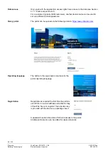
Page 46: ...e The portal can be queried via the following domain https www climatixic com The button in the upper right corner selects the portal operating language Registration is required the first time the portal is used Enter an e mail address and activation key of the Web Server to register The activation key is provided with the device as a package insert A password needs to be entered for future access...

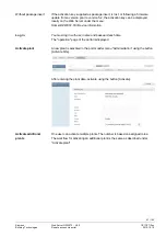
Page 47: ...X Device information You must log in with user name and password each time The operation page of the portal is displayed A new plant is activated in the portal under menu Administration using the button Activate Site After entering the plant data activate using the button Activate One user can activate multiple plants The number is based on assigned roles The workflow for activating an additional ...

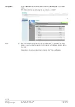
Page 48: ... can be queried by clicking the plant name The button Web access displays the user interface for OZW The user interface is opened in a new tab with button and have the exact same view as the direct connection to Web Server without portal local or via the Internet Operation is the same as described in Section 4 2 Operate the plant Query plant Note ...

Page 49: ... the owner possesses for the plant A predefined plant role can be used or a specific one defined A detailed description of plant roles is available in the portal s documentation 3 2 Prevent connection to portal The portal connection can be switched off if you do not want a connection to the portal Under path Home x x OZWx72 xx Settings Communication Services Is the data point Portal connection The...

Page 50: ... FF18 via USB interface LAN Ethernet or Internet with or without portal To access the portal enter the address https www climatixic com or https www siemens syncoic com For access without the portal enter the IP address for the interface USB Ethernet in the web browser s address line or the plant s domain name The login on portal or OZW User name Password Detailed information on user name and pass...

Page 51: ...dding the login information to the web browser s address line Format IP address main app user User name pwd myPassword Example 10 169 9 121 main app user Administrator pwd myPassword Only provide login information without private networks Do not create deep links with login information on public networks For access without portal you can create and save a deep link to go to a sub page without navi...

Page 52: ...top level of the menu tree From here you can go to all operating pages and data points Path Home 0 1 RVS61 843 109 Heating circuit 1 4 2 2 Operate Web Server Left click in the menu to select Web Server operation Web Server displays the top level of the menu tree From here you can go to all operating pages and data points Setting data on various operating pages is described in Section 2 5 Web Serve...

Page 53: ...ed to operate the Web Server from a smaller screen or to hide navigation Plant state Plant name Display The double arrow in the upper left hand corner switches the view In partial view navigation to other plant web pages must be implemented using user defined links You can return to the full view at any time for navigation Switch views Full screen Partial screen Note ...

Page 54: ...rmation Data point Explanation example Plant name Web Server or plant name Web Server type Web Server product number ASN Production number Device number from production System definitions Version of the loaded system definitions Software version Software version of the Web Server Build Revision status for the software Hardware version Web Server hardware version Field bus module 1 Field bus module...

Page 55: ...ization with bus devices Slave with remote setting Web Server receives time date from master The master supplies both date and time on the Web Server and is then sent to all bus devices Slave without rem setting Web Server receives time date from master The Web Server date time setting is not sent to the master The master resets date time Master Time date is created from the Quartz of the Web Serv...

Page 56: ... IP addresses on the subnet Devices must have the same partial network to communicate directly The factory setting for the Web Server subnet mask 255 255 255 0 Default gateway The Default gateway connects the subnetwork for the Web Server to additional networks e g the Internet The router typically is the default gateway Preferred DNS server Preferred DNS server Required to send e mails The router...

Page 57: ...S operating software is permitted on the Web Server With Off there is not access only via direct connection not possible via the portal Web access via http With On access is permitted with http and https With Off access is only permitted with https UPnP localization UPnP localization can be disabled or set on Ethernet or USB Portal connection With On data exchange with the portal is activated With...

Page 58: ...sponding device s web operation 4 3 2 Web Server faults You can display detailed information on all faults via the Home menu Displays all Web Server faults Path Home 0 5 OZW672 Faults current Local Data point Explanation example Fault 1 10 Displays for each fault Fault information date time fault code Fault text Overview of all Web Server faults included in Section 9 1 The most severe faults are d...

Page 59: ... CE1C5712en Building Technologies Operate using a web browser 2015 10 13 4 3 3 Faults Fault inputs 1 2 A fault at fault input 1 2 is displayed at Path Home 0 5 OZW672 Inputs Settings for fault inputs are described in Section 2 5 4 9 Faults ...

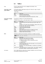
Page 60: ...and select desired file 5 The upload starts directly after selecting the desired files and clicking Open Make sure there is enough memory for uploading The Administrator and Service levels allow for uploading documents Procedure 1 Select Message history from secondary navigation 2 Click next to the desired document TXT for text or ASCII format and XLS for Excel Format The File download dialog box ...

Page 61: ...r entry Event Plant section i e device name LPB BSB address Date of occurrence Time of occurrence Fault code text Transmission date Transmission time Message receiver Cause Procedure 1 Select Logos from secondary navigation 2 Save existing logo s as needed see below 3 Click 4 Select the desired file Adhere to maximum dimensions see Notes 5 Click Upload 6 Reload page content from Web Server Interne...

Page 62: ...y navigation 2 Click Update 3 Select the desired file 4 Click Upload to finish 5 Upload is finished when the message Update Process finished displays 6 You must recreate the devices following a system definition upload System definition file transfer is available to administrator and service user levels Uploading and installing make take more than 15 minutes System definitions comprise Device desc...

Page 63: ...90 Commissioning with device search Popcard Plant diagrams For standard applications for the LPB BSB controller web capable plant diagrams may be exported from ACS790 and import them to the Web Server Parameterization Read and write parameter sets the OZW672 parameter set also includes the OZW672 device list Commissioning protocol Offline Trend For more details see data sheet N5649 ...

Page 64: ...ements Text elements Link elements Partial pictures Data point elements are used to operate and monitor read and write values for devices connected via the bus and the Web Server Plant web pages are generated online in the web browser The web page designer with administrator rights also switches the plant web pages to edit mode Other users can query and operate the last saved visualization during ...

Page 65: ...reduced setpoint Explanation text Link to Internet Integrated web cam image The example above is an extension to a web capable plant diagram downloaded from HIT The extension consists of additional explanatory text 3 a link to the Internet 4 and an integrated web cam image 5 that is updated periodically e g every minute Background image Data point element Text element Link element Partial picture ...

Page 66: ... for the last statement If an element is deleted as part of editing and another element added the new element jumps to the level of the deleted one This level is not always the top level You must add a new element as part of new editing to ensure that the new elements are placed at the top finish with OK and re click edit Plant web pages are hidden for a hidden device with appended plant web pages...

Page 67: ...web page Edit Switch to edit Copy Copy selected plant web page to another device node Export Export selected plant web page as tar archive Delete Deleted selected plant web page Click Edit to switch the plant web page to edit mode The toolbar is as follows Only an administrator may generate and change visualization User levels have the same rights for operation and monitoring Note View mode no web...

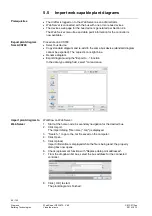
Page 68: ...orted The copied icon is light blue Rename diagram Export diagram using the Export to function In the data type dialog field select tar and save Workflow on Web Server 1 Start at the home node in secondary navigation for the desired bus 2 Click Import The import dialog file name tar is displayed 3 Search to go to the tar file saved on the computer 4 Click Open 5 Click Upload Import information is ...

Page 69: ... in red The cursor changes to a hand symbol when you move it over the display Click to open the applicable settings dialog box Set points are displayed in orange actual values in white For reasons of compatibility and regardless of the user level individual data points for the bus device may not be mapped to the plant diagram The data point text Data point not found is displayed Three question mar...

Page 70: ...ackground picture 6 Click Open 7 Click Upload The file name for the selected picture is displayed in the background picture field 8 Click OK The plant web page is now saved with the background picture The anchor for the X Y position of the background image is fixed on the plant web site in the full image at180 194 pixels left top corner of the image This corresponds to 10 86 pixels in the partial ...

Page 71: ...is note refers as well to text and link elements accordingly Alignment x Left Data point text Data point value x Center Data point text Data point value x Right Data point text Data point value The x displays the changed position of the anchor The alignment of all the data point texts is left aligned The following describes how to add informational text to a plant web page 1 Click Edit The plant w...

Page 72: ...get web page to return to the previous page Links are broken after importing a plant web page to another Web Server and must be restored per the instructions above The links to other plant web pages are also broken after a firmware update for web pages exported in advance and then imported and must be restored per instructions above 1 Click Edit The plant web page switches to edit 2 Click Link The...

Page 73: ...ling 10 Click Apply to check the results of formatting in a preview 11 If satisfied click OK to finish 12 Click OK to change to view 1 Click Edit The plant web page switches to edit 2 Click Partial picture The partial picture dialog box is displayed 3 Select Picture source in Link external field 4 Opens the web cam image on the Internet 5 Right click webcam image 6 Select properties for webcam ima...

Page 74: ...ion They do not represent process or safety limit values which trigger e g fault messages or turn off the plant in the event of limit violations Users also are allowed to change data point values setpoints E mail messages from the system then remind the user that a value or values were changed Green leaf à Green tree leaf leaf pointing up The Green leaf symbol indicates that a data point value has...

Page 75: ... value Room temperature Comfort setpoint HC1 and its Green limit 6 1 2 LPB BSB bus topology The OZW672 01 Web Server can monitor 1 bus device via the Energy indicator function The OZW672 04 Web Server can monitor up to 4 and OZW672 16 up to 16 bus devices via the Energy indicator function A maximum processing time of ca 40 minutes results for the max quantity of Energy indicator data points Exampl...

Page 76: ...ist in the Device description can be changed 6 1 4 Navigation and device web pages Go to the Energy indicator function as follows Via primary navigation main function Energy indicator Click the Plant state Energy indicator pane top right field pane tree leaf in the screenshot below On the web page you can select the Energy indicator function from the primary navigation next to Home In secondary na...

Page 77: ... 2 6 for information on the summary display The Energy indicator for devices is displayed at the Plant level in the Energy indicator column for each device Clicking the name of a device in secondary navigation or in the Device name column opens the next lower level for that device Energy indicator tree leaf for each actively monitored device This column also contains Checkboxes to activate deactiv...

Page 78: ...plex devices see partial plants below for RVS Heating controller Clicking the name of a partial plant in secondary navigation or in the Partial plant name column opens the next lower level for that partial plant Clicking in secondary navigation opens the next higher level Energy indicator tree leaf for each actively monitored partial plant This column also contains the checkboxes to activate deact...

Page 79: ...or each actively monitored data point This column also contains the checkboxes to activate deactivate Energy indicator monitoring of the selected data point deactivate without confirmation message Name of the data point Value of the data point dependent on data point type with unit e g C Clicking the red pen symbol opens the dialog box for the selected data point see Section 6 4 Value of the set G...

Page 80: ...number of data points y that could be monitored x of y is displayed for each device and partial plant in the corresponding row The sum of all devices and partial plants is displayed in the bottom row x of y is displayed for each partial plant in the corresponding row and the sum of all partial plants is displayed in the bottom row Level Data points does not have indication x of y Column Monitored ...

Page 81: ...ured at the Administrator access level and Service in the Web Server Path OZW672 Settings Energy indicator Energy indicator on the web very bottom of web page Energy indicator remains active even if Energy indicator on the web Not visible is selected Configuration Energy indicator on the web Visible Not visible also applies to user groups Service and End user Configuration of visibility Notes ...

Page 82: ...Web Server front mean LED is lit green Energy indicator of the plant Green leaf LED is lit orange Energy indicator of the plant Orange leaf Green leaf All actively monitored data points of the plant are within limits i e no Green limits are violated Orange leaf At least one monitored data point is outside its Green limit The number of data points outside their Green limit is displayed in addition ...

Page 83: ...displayed as part of the Energy indicator function The Energy indicator database only exists on the Web Server And the Web Server itself has no data points subject to the Energy indicator function is temporarily displayed for a data point s status in the Value column until the data point value is read and processed via the bus A maximum of 4 Energy indicators per second are updated on a web page T...

Page 84: ... start up mode The Green leaf display does not necessarily reflect the current plant state prior to completion of the Estimated processing time The updated display of Energy indicator can be postponed by max the Estimated processing time Note the restriction from the updated Energy indicator display also when navigating to other web pages 6 3 4 Deactivating Data point monitoring Monitoring Energy ...

Page 85: ...tivated No confirmation message is displayed when data point monitoring is deactivated A confirmation message is displayed when data point monitoring for a device or plant is deactivated Clicking Yes for message Really to be continued to deactivate monitoring also resets Green limits changed by the user to their default values Therefore Monitoring off deactivates monitoring while at the same time ...

Page 86: ...ated by user Data point monitoring activated Selecting the checkbox activates the data points for the selected device Selecting the summary checkbox green red bottom row activates the data points for the plant Selecting the checkbox activates the data points for the selected partial plant Monitoring is deactivated for partial plant Cooling circuit 1 As a result all data points are deactivated Cool...

Page 87: ...ted Activating just one data point also activates the partial plant A data point Release cooling circuit 1 of partial plant Cooling circuit 1 is activated Partial plant Cooling circuit 1 is automatically activated Note that Monitoring activated at the Partial plants level does not mean that all subordinate data points are activated and monitored also This also applies to Monitoring activated at th...

Page 88: ...ge 16 0 C to 35 0 C for data point and Green limit s The set data point value is displayed in the field above the setting range There are 3 ways to change the data point value Change the data point value in the entry field Move the data point slider to the right or left Arrows to adjust the value step by step The data point slider is green for as long as the data point value is within the green se...

Page 89: ...values can be regenerated only by deactivating Data point monitoring with summary checkbox 6 4 2 Dialog boxes with numeric data points In numeric data points such as Room temperature Comfort setpoint HC1 the Green limits may depend on neighboring values Therefore To achieve the desired setting range the data points heating circuit and cooling circuit setpoints and their Green limits must be set in...

Page 90: ... values at least one Green limit for a value to be monitored needs to be set The enumeration values are predefined as per the data point type The Green limit s are set by clicking the selection boxes 6 4 4 User groups Service and End user The dialog boxes for the Energy indicator data points can be opened also in the Service and End user user groups The entry fields of values that cannot be set ar...

Page 91: ...idually separate settings If Transmit time 1 and or 2 are configured the Energy indicator of the plant is sent as an e mail only if at least one monitored data point exceeds its Green limit Configuration of e mail receivers 1 and 2 for the Energy indicator of the plant is not related to the e mail receivers of fault messages device failure etc One e mail each can be sent for test purposes to E mai...

Page 92: ... mail server address mail server port number e mail address recipient mail server authentication network cable Manual triggering for test purposes does not trigger a fault message If an e mail with Energy indicator of the plant is not transmitted without error a fault message is triggered for the corresponding e mail recipient The fault message is reset if The next transmitted e mail is transmitte...

Page 93: ...Plant name OZW type or user defined name see examples Energy indicator Fixed text e g Energy indicator translated into the language selected in the Web Server OZW672 16 Energy indicator Landmatt 1 Energy indicator The actual message is written in the language selected in the Web Server 2 of 117 monitored data points have crossed their Green limits 10 lines follow this text where each line may cont...

Page 94: ...t the Energy indicator data is deleted also In the event of bus device failure e g no communication via LPB BSB bus the Grey leaf is displayed The Estimated processing time does not change If there is no bus supply the data point values of the bus devices cannot be read and a Grey leaf is displayed The Estimated processing time does not change Complete system data updates for all bus devices via G...

Page 95: ... connections must be suppressed The Web Server can be operated from a PC with web browser on a local area network LAN or via the Internet The following settings also apply to access via Smartphone and other apps via Web API 7 1 1 Access via portal OZW registers automatically during commissioning as soon as it connects to the Internet All functions are available after the user also logs on to the p...

Page 96: ...e router via Ethernet an IP address subnet mask standard gateway and DNS server are assigned automatically When delivered the Web Server already contains an enabled DHCP client as a result users do not need to enter Ethernet settings The connection is checked every 3 minutes It is recommended to assign the IP address of the Web Server in the router according to its MAC address If the router with D...

Page 97: ...the PC uses 192 168 2 199 and the router uses 192 168 2 1 Subnet mask 255 255 255 0 Default gateway 192 168 2 1 Preferred DNS server 192 168 2 1 Alternate DNS server empty In the example the subnet has an address of 192 168 2 x Devices must have the same subnet address to communicate directly i e without a router The Web Server is delivered as preconfigured DHCP client with automatic reception of ...

Page 98: ...k is installed with PC and Web Server but without DHCP server normally in the router On the PC set as follows 1 Select Start Control Panel Network Connections Local Area Connection 2 Select the General tab 3 Click Properties 4 Select Internet Protocol TCP IP 5 Click Properties 6 Select Use the following IP address Continued on the next page Local area network without router ...

Page 99: ...ubnet e g 192 168 2 10 Subnet mask 255 255 255 0 Default gateway empty Preferred DNS server empty Alternate DNS server empty In the example the subnet has an address of 192 168 2 x Devices must have the same subnet address to communicate directly i e without a router The default gateway and DNS server settings have no meaning for LANs without router provided no e mail is sent within the home netwo...

Page 100: ...pports HTTPS Hyper Text Transfer Protocol Secure Web operating pages are transmitted secured and encrypted The user is responsible for the use of unencrypted HTTP connection Use a VPN connection is accessing via a fixed IP address IP address subnet mask and DHCP are set up under Local Network in addition to other settings The IP address router is fixed The subnet mask defines the size of the subne...

Page 101: ...t renews the IP addresses of the DHCP clients every 30 in the above example minutes DHCP clients are assigned addresses from a range of 192 168 2 100 through 192 168 2 199 The router is the gateway between LAN and Internet We recommend enabling the firewall to protect the local area network Firewall On Activate NAT to ensure that the Web Server can be reached via the Internet NAT On Firewall Addre...

Page 102: ... also change Port 21 FTP and Port 50005 ACS private from the public to a private IP address The port IP address is appended to the web browser address line IP address Port e g 122 104 2 10 80 The web browser always uses port 80 unless another port is entered As a result the information in the address line for the web browser is always IP address 80 and IP address or 122 104 2 10 80 and 122 104 2 1...

Page 103: ...me own name User name User name for the Dynamic DNS account e g MyUserAccount Password Password for Dynamic DNS account HTTPS encryption via port 443 is also supported The required certificate is not accredited The self signed certificate from Siemens is valid for 20 years and is installed on the Web Server The certificate must be installed on the web browser for encrypted communications One own c...

Page 104: ...and trend data via email The mail server SMTP server out going mail server must be known to the Web Server to send e mails to the receivers The following applies to send e mails via the Internet An e mail account is available and set up Internet access is set up for the Web Server see Section 7 1 3 The settings for E mail Message receiver 1 4 System report see Section 2 5 4 E mail Example mail ...

Page 105: ...t Device Demo HCS 0 5 Texts Name Device address Message No bus power supply Fault text Fault number 81 Fault code Fault priority Urgent Fault priority Occurred at 15 09 2009 at 08 44 Occurred at myhome dyndns info Communication E mail Signature line 1 10 Example of an e mail Data point information From myhome bluewin ch Communication E mail E mail address sender To service siemens com Message rece...

Page 106: ...t input 1 2 Text for Fault Text for No fault Fault number 171 00 Fault code Fault priority Not urgent Faults Local Fault input 1 2 Fault priority Occurred at 15 09 2009 at 08 44 Occurred at myhome dyndns info Communication E mail Signature line 1 10 Example of an e mail Data point information From myhome bluewin ch Communication E mail E mail address sender To service siemens com Message receiver ...

Page 107: ...evice Demo HCS 0 5 Texts Name Device address Message No bus power supply 81 Fault text fault code Occurred at 15 09 2009 at 08 44 Occurred at myhome dyndns info Communication E mail Signature line 1 10 Example of an e mail Data point information From myhome bluewin ch Communication E mail E mail address sender To service siemens com Message receiver Message receiver 1 4 E mail address Subj System ...

Page 108: ...ion if required 8 Click Cancel to exit the account settings A list of providers that send e mails at no charge is available in Section 9 3 2 The Web Server supports HTTPS Hyper Text Transfer Protocol Secure E mails are transmitted unsecured and unencrypted Web Server supports SSL Secure Sockets Layer network protocol for the secure transfer of data and TLS Transport Layer Security encryption proto...

Page 109: ... sampling rate A web browser is used to set the Trend As an alternative you can also set Trends via the ACS Tool 1 Select the Web Server The Home page is displayed 2 Under primary navigation select File transfer menu In secondary navigation on the left side of the window the overview page Trend for the Web Server is automatically selected The Trend overview is displayed as follows if no Trend has ...

Page 110: ...definitions Download Trend data Delete Trend data and Trend definitions A Trend channel can have the following states Invalid Trend is state invalid as long as no data points are defined in Trend e g in delivery state or after deleting a Trend definition Process completed The Trend is in state Process completed as soon as data points are defined that the Trend is stopped or not yet started Running...

Page 111: ... h 4 Click to add a data point The Data point address window is displayed with available devices 5 To record the outside temperature data point Outside temperature under RVS43 143 109 Info is used in this example 6 The Trend settings and the resulting maximum Trend length and bus load are displayed in the Edit window Click to add up to a maximum of 100 data points To finish confirm the settings wi...

Page 112: ...a points are listed in the trend file csv with a The missing data points are displayed as a break in the curve for the trend graph Trends are synchronized to simplify evaluation of trend data The various query intervals are set up on an interval grid The interval grid begins at 00 00 00 hh mm ss A newly started trend displays the first data point at the first possible interval point after start Th...

Page 113: ...of 100 As a consequence an additional query of the room temperature at 50 load can no longer be started Any attempt to start this Trend results in a warning 8 2 3 Reset Trend definition Trends can be reset to the default settings The default settings for the values are as follows Interval 15 Min Number of data points 0 Status Invalid Rolling trend days Bus load 0 Trend name Any associated Trend da...

Page 114: ... 1 Click the red pencil to open the existing Trend The Edit window opens 2 Use the plus symbol to add an additional data point address as data point to the Trend The selected data points are listed in the data point list 3 You can add a maximum of 100 data points to the Trend using the plus symbol Bus load and Trend period is adapted to the number of data points accordingly Add data points ...

Page 115: ...size is assigned to each Trend channel Trend channel 1 has more memory and is particularly well suited for long term Trending with a number of data points or a high query interval Trend channel 1 14 MB Trend channel 2 5 2 MB The read data is written first to RAM while Trending It is transmitted to flash memory every 60 minutes A maximum of one hour of Trend data is lost in the event of a power out...

Page 116: ...it window opens 3 Enter the desired e mail address 4 Click OK You can send a test e mail to the receiver to ensure the settings are correct 1 Click Test receiver or the red pencil symbol 2 In the Edit window select Trigger 3 Confirm with OK OZW sends a test e mail to the entered receiver and confirms transmission under data point Trend data sent with Yes If transmission failed a possible cause is ...

Page 117: ...r maximum data content has passed Trend channel 1 ca rolling trend 14 channel 1 is 7 x greater than Channel 2 5 Trend channel 2 5 ca rolling trend 2 Daily An e mail is sent daily The trend data for the past day is sent Weekly An e mail is sent each Monday Trend data is sent for the past week but at the maximum number of days for the maximum data content Monthly An e mail is sent on the first day o...

Page 118: ...ission to receiver 1 2 8 3 3 E mail contents and appendix The plant and Trend name is displayed in the subject line for the e mail The file name of the appendix is composed as follows Trend_data_x_ with x representing Trend channel 1 5 Creation date yyyymmdd In addition the text field lists the current status of the corresponding Trend State Running Trending is still running State Completed Trendi...

Page 119: ...erval Beginning End last Trend item prior to transmitting Trend data Path and data point name of Trend 8 4 Download Trend file via web Trend data can be downloaded via the OZW web user interface Downloading via the web does not influence transmission of the data by e mail Logging of Trend data continues unabated while downloading via web Trend data is downloaded via web as follows 1 Under primary ...

Page 120: ...displayed under Circular logging 4 Click the calendar symbol to select the beginning and end of the period and select the desired day The period always begins at 00 00 and ends at 23 59 of the selected day 5 Click OK to confirm the period 6 The Export window may be displayed for larger amounts of Trend data The window is skipped for smaller files Files can be exported whether trends are ongoing or...

Page 121: ... and hidden in the checkbox The red framed master checkbox selects and clears all data series Only the selected data point series are displayed in the key Key of curves with associated color and name of the data point series Time axis with data and time Unit axis as per the data point series The content of the graph can be zoomed in out by scrolling The cursor can move the position of the graph Mo...

Page 122: ...ons The logged Trend data is neither exported nor imported 1 Under primary navigation select File transfer menu see Section 8 1 Overview 2 On the desired Trend channel click Export symbol 3 In the following window select Save file The views differs by browser The file name is formed as follows Trendx trx with x representing Trend channel 1 5 The Trend definition can be exported during Trending On ...

Page 123: ...lick OK 6 The name of the selected file is displayed in the window 7 Click OK 8 The data point address must be changed in the following window if the device of the Trend definition for import does not match with the device on the plant true even if the data point matches the data point address is specific to the device 9 Select checkbox 10 Select the desired data point address from the drop down l...

Page 124: ...ata of the Trend channel is deleted 15 Click OK Trend data is imported and the Trend goes to the defined state as per the imported file A Trend exported in the state Running is started automatically after the import is completed as long as bus load does not exceed 100 A Trend exported in state Completed is not started after import A Trend definition can be copied as follows within the same OZW 1 E...

Page 125: ...not be read and are therefore unavailable The ACS writes its trend definition in the first as viewed by ACS available trend channel As a result a trend defined for the web can be overwritten without warning As of ACS V9 01 the ACS and OZW trend definitions are compatible The trends can be defined in ACS or OZW The trend in OZW synchronizes if an explicit start time is selected in ACS when defining...

Page 126: ...aximum possible load A trend written via ACS automatically switches to the status set in the trend definition The bus load of an ACS trend is displayed using the current value The trend switches automatically to the status set in the trend definition For the trend definition Process running the trend only starts if the resulting overall bus load does not exceed 100 ACS V9 00 or older ACS as of V9 ...

Page 127: ...s connected 439 Bus module not identified 448 Message receiver 1 not reached 3 449 Message receiver 2 not reached 3 450 Message receiver 3 not reached 3 451 Message receiver 4 not reached 3 486 Energy ind receiver 1 not reached 487 Energy ind receiver 2 not reached 512 Trend receiver 1 not reached 513 Trend receiver 2 not reached System configuration errors 82 1 identical device address Devices ha...

Page 128: ...ane 3 Click OK 4 Enter the desired command in the command line C Command Result application ping IP address or domain Response times to the query Checks whether an IP address can be reached in the network Tracet IP address or domain Progress of the IP address implementation to the goal Check whether DNS and mail servers can be reached nslookup IP address or domain Translates an IP address to the d...

Page 129: ...al network e g for operate Monitor via KNXnet IP 9 3 2 Free e mail account providers You can use free of charge e mail accounts to send e mails Note that some ISPs work with encryption or can be accessed and used only via the Web Server s DSL connection The following list is not conclusive ISPs are subject to change Free e mail account providers Address mail server Port mail server Authentificatio...

Page 130: ...stalled The driver is installed in the background using an Internet connection You can install the driver manually without an Internet connection The operating system must be equipped with the latest updates Procedure 1 Select Search for and install the hardware automatically Recommended 2 Click Next The software is installed 3 Confirm hardware installation Click Continue installation 4 Wait until...

Page 131: ...on the PC Following the steps for the installation wizard The RNDIS driver is now installed The PC can communicate with the Web Server via USB The RNDIS driver is installed as part of the ACS790 Siemens software installation 9 3 4 Alternative network configuration We recommend setting up IP settings for commissioning as an alternative configuration if a PC connected to a network is temporarily use...

Page 132: ...Select Internet Protocol TCP IP 5 Click Properties 6 Select Alternate Configuration tab 7 Enter IP address subnet mark and operational standard gateway as well as DNS server The PC assumes the configuration with these settings as soon as it is no longer integrated in the standard network Result ...

Page 133: ...al Subscriber Line see DSL DNS The DNS allows for assigning IP addresses to names that are easier to remember than 32 bit IP addresses A DNS server must manage this information for each LAN with Internet connection When you select an Internet page the web browser accesses the IP address of that site assigned by the DNS server to open a connection On the Internet domain names are assigned to IP add...

Page 134: ...Internet under the same domain name regardless of the current IP address A domain name can be registered with a Dynamic DNS service Ethernet Ethernet is a network technology for local networks LAN Ethernet operates at a transmission rate of 10 or 100 Mbps and has a maximum range of 100 meters between two network components Firewall A firewall protects networks against unauthorized access from the ...

Page 135: ...n names are used rather than IP addresses The DNS server assigns domain names to IP addresses IP address pool IP address pool defined at the router IP address range the DHCP server can be used to assign dynamic IP addresses LAN A local network size large building building sites is a number of interconnected network devices In LANs data is exchanged and resources are used jointly A LAN can be conne...

Page 136: ...der of the data package with the network Internet service applications work with set port numbers HTTP 80 FTP 21 See http www iana org assignments port numbers for registered port numbers Port numbers 0 to 49151 are set and reserved port numbers 49152 to 65535 are dynamic and therefore available Port and Address Translation See PAT Port Forwarding With port forwarding the router forwards data pack...

Page 137: ...e a virtual Ethernet when communicating between the device and a computer via USB Router A router forwards data packages from a local network LAN to a higher network while selecting the fastest route A router allows for connecting different networks with different network topologies For example the router connects a local network to the Internet Secure Sockets Layer See SSL Server A server accepts...

Page 138: ...col TCP reassembles the data packages sent by the Internet protocol IP via different network connections in the right order at the recipient TCP IP Family of protocols used as the basis for the Internet TCP IP for the basis for any number of internet services such as HTTP Web FTP file transfer and SMTP mail TLS TLS Transport Layer Security for outdated SSL Secure Sockets Layer a hybrid encryption ...

Page 139: ...location of the resource on the network User Datagram Protocol See UDP WAN The wide area network WAN has a spatial dimension of ca 50 km A WAN can comprise a number of several LANs If an ISP operates a WAN private LAN users receive access to the Internet Wide Area Network See WAN Wireless LAN See WLAN WLAN Wireless LANs allow network devices to communicate via radio The WALN can be added as an ext...

Page 140: ...ription 76 Device information 54 Ethernet 56 LPB BSB 55 Services 57 Dialog box Energy indicator Data point value 88 Enumeration data points 90 General 88 Green limit s 89 Numeric data points 89 Setting range 88 Display and operating elements 9 Dynamic DNS 103 E Edit data point address 123 E mail Receiver 118 Test receiver 116 Transmission options 117 Transmit interval 117 Trend data 115 E mail Ene...

Page 141: ...g languages 46 Prevent access 49 Roles 49 Primary navigation 10 R Remote access via portal 45 Remote operation via the Internet 100 S Secondary navigation 10 Services 30 57 Set up portal access 45 Settings ACS access 30 Automatic log off 30 Communication 27 Email Email address sender 29 Mail server address 29 Mail server port number 29 Ethernet IP address 28 Subnet mask 28 Fault input 1 2 34 Fault...

Page 142: ...mory 115 Reset 113 Transmission options 117 Transmit interval 117 Trend functions 109 U Updates 44 UPnP localization USB 29 UPnP Localization Ethernet 30 User levels 12 User name 18 V Valid characters 127 Visibility Energy indicator 81 Visualize 64 W Web operation user interface 10 Web page Energy indicator function 75 Energy indicator update 83 Web server diagnostics 54 Web server faults 58 Web s...

Page 143: ...ilding Technologies 2015 10 13 Siemens Switzerland Ltd Building Technologies Division International Headquarters Gubelstrasse 22 6301 Zug Switzerland Tel 41 41 724 24 24 www siemens com buildingtechnologies Siemens Switzerland Ltd 2010 Subject to change ...

Reviews: