Document No. 545-407
Installation Instructions
February 7, 2003
Information in this publication is based on current specifications. The company reserves the right to make changes in specifications and
models as design improvements are introduced. Other product or company names mentioned herein may be the trademarks of their
respective owners. © 2003 Siemens Building Technologies, Inc.
Siemens Building Technologies, Inc.
1000 Deerfield Parkway
Buffalo Grove, IL 60089-4513
U.S.A.
Your feedback is important to us. If you have
comments about this document, please send
them to [email protected]
Document No. 545-407
Printed in the U.S.A.
Page 2 of 2
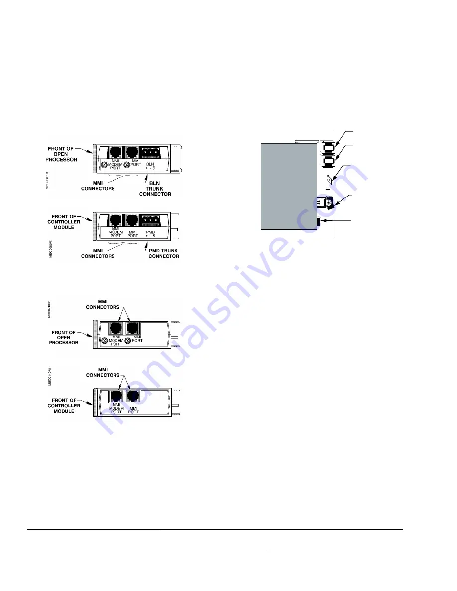
MBC/RBC
Insert the RJ-11 plug of the extension cable
into the MMI port on the right side of the Open
Processor or Controller Module (Figure 4 and
Figure 5).
The installation is now complete.
Figure 4. MBC/RBC P2 MMI Ports
Open Processor or Controller Module.
Figure 5. MBC/RBC Stand-alone MMI Ports
Open Processor or Controller Module.
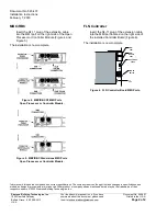
FLN Controller
Insert the RJ-11 plug of the extension cable
into the MMI port located on the right side of
the installed Controller Board (Figure 6).
The installation is now complete.
FLN0007R1
12
VDC
MMI
PORT
MMI
MODEM
PORT
POWER
SWITCH
ON 1
OFF 0
GROUNDING
SPADE
JP2
Figure 6. FLN Controller Board MMI Ports.


