


LMV Series
Technical Instructions
LV5-1000
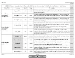
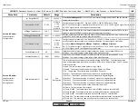
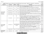
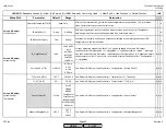
Menu Path
Parameter
Default
Range
Description
51.1
52.2
52.4
LEGEND -
Password Access:
(U)=User, (S)=Service, (O)=OEM, Shaded = Commonly Used, ** = Must Set, X = Has Function, / = Partial Function
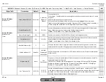
LMV
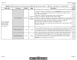
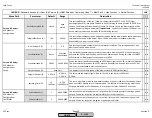
CurrMode 0/4mA (S)
0..20mA
0..20mA
4..20mA
Selects the output signal of X63 to be either a 0-20mA signal or a 4-20mA signal. NOTE: This
has no effect when
OutValueSelection
is set to "Load".
x x x
Scale20mA perc (S)
100%
0-999.9%
Scales the analog output for the percent values (other than Load). Specifically, this
parameter defines what percentage of Load 0, O2, Speed VSD, or Flame will output 20mA.
x x x
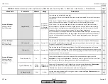
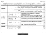
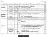
Scale20mA temp (S)
1562 F
32-3632 F
Scales the analog output for the temperature values. Specifically, this parameter defines
what temperature (read by Temp Pt1000,Temp Ni1000, etc.) will output 20mA.
x x x
Scale20mA press (S)
2 PSI
0-1449 PSI
Scales the analog output for the pressure value. Specifically, this parameter defines what
pressure (read by Press X61) will output 20mA.
x x x
Scale20mA angle (S)
90 deg
0-90 deg
Scales the analog output for the actuators. Specifically, this parameter defines what angular
degrees will output 20mA.
x x x
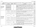
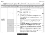
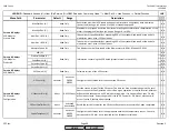
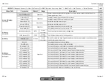
Scale 0/4mA (S)
0%
0-999.9%
Sets the start of the scale for every process value other than "Load". (The start of the scale
"Load 0" can be set here, but if "Load" is selected this parameter has no effect.) For example
: If parameter
OutValueSelection
is set to "Pos Air",
CurrMode 0/4mA
is set to 4mA,
Scale20mA angle
is set to 90 deg, and
Scale 0/4mA
is set to 0%, then 12 mA will be output
when the air actuator is at 45 degrees, and 20mA will be output at 90 degrees. If all other
values are unchanged and
Scale 0/4mA
is now set to 50%, then 4 mA will be output when
the air actuator is 45 degrees, and 20mA will be output when the actuator is at 90 degrees.
x x x
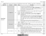
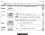
StartAdaption (U)
This starts the adaption process. During the adaption process, the LMV5 will determine the
thermal response of the system (burner / boiler and attached thermal users). Values for PID
will be calculated based on this information. The LMV5 does this by modulating to minimum
load and letting the system "settle" to a particular pressure or temperature. After this
"settling" period, the LMV5 will modulate up to the
AdaptionLoad
and see how long it takes
for the system temperature / pressure to respond.
Based off of this response, the LMV5 will choose values for P, I, and D. These calculated
values are implemented by choosing "Adaption" under
StandardParam
.
NOTE: Adaption has to be started when the burner is running and a representative load
exists on the system.
x x x
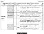
AdaptionLoad (U)
100%
40-100%
This load is used to determine the thermal response of the system during adaption only.
LMV5 will travel to this load during the heating phase of the adaption.
x x x
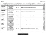
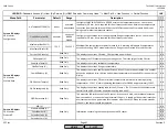
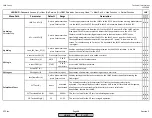
Params & Display>
LoadController
SW Version (U)
Software version of the load controller.
x x x
Params & Display>
LoadController>
Configuration>
Analog Output
Go into parameter and
then press Enter to start
adaption
Read Only
Params & Display>
LoadController>
Adaption
SCC Inc.
Page 35
Section 3
HOME
HOME
P - LIST
Summary of Contents for LMV 5 Series
Page 2: ...Intentionally Left Blank ...
Page 41: ...LMV Series Technical Instructions Document No LV5 1000 SCC Inc Page 7 Section 2 HOME ...
Page 42: ...Technical Instructions LMV Series Document No LV5 1000 Section 2 Page 8 SCC Inc HOME ...
Page 43: ...LMV Series Technical Instructions Document No LV5 1000 SCC Inc Page 9 Section 2 HOME ...
Page 44: ...Technical Instructions LMV Series Document No LV5 1000 Section 2 Page 10 SCC Inc HOME ...
Page 45: ...LMV Series Technical Instructions Document No LV5 1000 SCC Inc Page 11 Section 2 HOME ...
Page 46: ...Technical Instructions LMV Series Document No LV5 1000 Section 2 Page 12 SCC Inc HOME ...
Page 47: ...LMV Series Technical Instructions Document No LV5 1000 SCC Inc Page 13 Section 2 HOME ...
Page 48: ...Technical Instructions LMV Series Document No LV5 1000 Section 2 Page 14 SCC Inc HOME ...
Page 49: ...LMV Series Technical Instructions Document No LV5 1000 SCC Inc Page 15 Section 2 HOME ...
Page 50: ...Technical Instructions LMV Series Document No LV5 1000 Section 2 Page 16 SCC Inc HOME ...
Page 51: ...LMV Series Technical Instructions Document No LV5 1000 SCC Inc Page 17 Section 2 HOME ...
Page 52: ...Technical Instructions LMV Series Document No LV5 1000 Section 2 Page 18 SCC Inc HOME ...
Page 53: ...LMV Series Technical Instructions Document No LV5 1000 SCC Inc Page 19 Section 2 HOME ...
Page 54: ...Technical Instructions LMV Series Document No LV5 1000 Section 2 Page 20 SCC Inc HOME ...
Page 55: ...LMV Series Technical Instructions Document No LV5 1000 SCC Inc Page 21 Section 2 HOME ...
Page 373: ...Intentionally Left Blank ...