

LMV Series
Technical Instructions
LV5-1000
Menu Path
Parameter
Default
Range
Description
51.1
52.2
52.4
LEGEND -
Password Access:
(U)=User, (S)=Service, (O)=OEM, Shaded = Commonly Used, ** = Must Set, X = Has Function, / = Partial Function
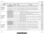
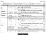
LMV
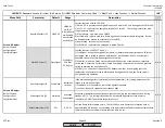
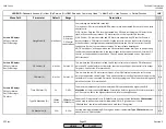
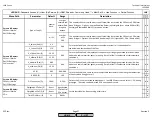
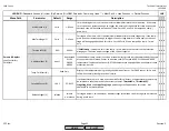
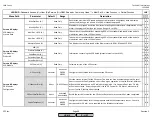
CombEfficiency (U)
Calculated combustion efficiency, based on wet O2 levels in the stack,
combustion air temperature, and flue gas temperature.
x x
ManVar O2 Ctrl (U)
This value represents how much the O2 control is trimming. Values less than 50% indicate
that the air-influenced actuators are farther closed than when the O2 was commissioned.
Values greater than 50% indicate that the air-influenced actuators are farther open than
when the O2 was commissioned. When air temperature decreases (and air density
increases), this value should decrease. Conversely, when air temperature increases (and air
density decreases), this value should increase.
x x
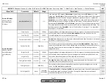
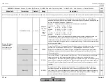
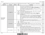
State O2 Ctrl (U)
This displays the status of the O2 trim control.
1) deactivated - O2 trim is manually or automatically deactivated. System operates on ratio
control curve.
2) locked - the manipulated variable (amount of trim) is held at the last value.
3) LockTStart - trim is waiting to engage after lightoff. See
NumberTauSuspend
.
4) InitContr - controller is being initialized (preparing to trim) and is still locked.
5) LockTLoad - the O2 trim is engaged but locked due to a load change. See parameter
LoadControlSuspend
.
6) active - the O2 trim is active and adjusting the air rate in small steps to achieve the O2
setpoint.
7) LockTCAct - the O2 trim is engaged but locked due to an excursion from O2 setpoint.
x x
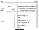
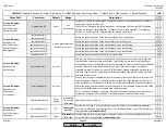
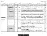
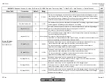
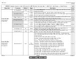
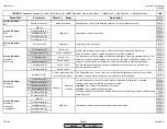
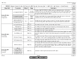
Air-related Load (U)
This is the load-position of the air influenced actuators. If this number is less than the fuel
related load at a given point, the air influenced actuators are trimming closed. If greater,
than the air influenced actuators are trimming open.
x x
Diag Reg State (U)
If
State O2 Ctrl
reads "locked", this diagnostic code reveals other information.
These diagnostic codes are:
0 = load is below load limit set in parameter
O2 CtrlThreshold
.
1 = the load controller is in auto-tune or in manual mode.
2 = the O2 sensor is being tested for response (the LMV5 does this periodically during
operation).
3 = the fuel air ratio curves or the O2 trim curves are being programmed.
4 = the measured %O2 is below the %O2 set in the Low O2 Alarm curve.
5 = error in the PLL52 module.
6 = error in the precontrol.
x x
Read Only
Read Only
Params & Display>
O2Contr/Alarm>
Process Data
Read Only
Read Only
Read Only
SCC Inc.
Page 28
Section 3
HOME
HOME
P - LIST
Summary of Contents for LMV 5 Series
Page 2: ...Intentionally Left Blank ...
Page 41: ...LMV Series Technical Instructions Document No LV5 1000 SCC Inc Page 7 Section 2 HOME ...
Page 42: ...Technical Instructions LMV Series Document No LV5 1000 Section 2 Page 8 SCC Inc HOME ...
Page 43: ...LMV Series Technical Instructions Document No LV5 1000 SCC Inc Page 9 Section 2 HOME ...
Page 44: ...Technical Instructions LMV Series Document No LV5 1000 Section 2 Page 10 SCC Inc HOME ...
Page 45: ...LMV Series Technical Instructions Document No LV5 1000 SCC Inc Page 11 Section 2 HOME ...
Page 46: ...Technical Instructions LMV Series Document No LV5 1000 Section 2 Page 12 SCC Inc HOME ...
Page 47: ...LMV Series Technical Instructions Document No LV5 1000 SCC Inc Page 13 Section 2 HOME ...
Page 48: ...Technical Instructions LMV Series Document No LV5 1000 Section 2 Page 14 SCC Inc HOME ...
Page 49: ...LMV Series Technical Instructions Document No LV5 1000 SCC Inc Page 15 Section 2 HOME ...
Page 50: ...Technical Instructions LMV Series Document No LV5 1000 Section 2 Page 16 SCC Inc HOME ...
Page 51: ...LMV Series Technical Instructions Document No LV5 1000 SCC Inc Page 17 Section 2 HOME ...
Page 52: ...Technical Instructions LMV Series Document No LV5 1000 Section 2 Page 18 SCC Inc HOME ...
Page 53: ...LMV Series Technical Instructions Document No LV5 1000 SCC Inc Page 19 Section 2 HOME ...
Page 54: ...Technical Instructions LMV Series Document No LV5 1000 Section 2 Page 20 SCC Inc HOME ...
Page 55: ...LMV Series Technical Instructions Document No LV5 1000 SCC Inc Page 21 Section 2 HOME ...
Page 373: ...Intentionally Left Blank ...