


LMV Series
Technical Instructions
LV5-1000
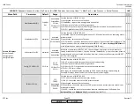
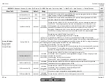
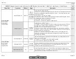
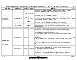
Menu Path
Parameter
Default
Range
Description
51.1
52.2
52.4
LEGEND -
Password Access:
(U)=User, (S)=Service, (O)=OEM, Shaded = Commonly Used, ** = Must Set, X = Has Function, / = Partial Function
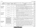
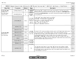
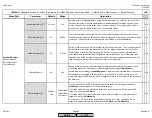
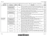
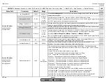
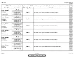
LMV
Startmode (O)
standard
standard
Ign Load TC
IgnPtWithTC
IgnPtWoutTC
Sets how the LMV52.4 transitions from lightoff to operation. Four possibilities exist:
1) standard - after lightoff at set ignition positions, LMV5 is immediately released to
modulate on the position control (fuel air ratio) curves. O2 trim will engage after a period of
time defined by (
Tau Low-Fire
x
NumberTauSuspend
) plus an additional 4x
Tau Low-Fire
.
This is how past LMV52s have functioned.
2) Ign Load TC - does not use set ignition positions. Varies ignition positions based on
ambient temperature and the setting of parameter
Load of Ignition
.
3) IgnPtWithTC - uses set ignition positions, but will vary the positions of the air influenced
actuators when transitioning from lightoff to low fire based on ambient temperature.
4) IgnPtWoutTC - uses set ignition positions, and will vary the positions of the air influenced
actuators when transitioning to low fire based on learned characteristics of the burner.
NOTE: Start modes other than standard will all hold the LMV5 at
StartPointOp
(low fire)
until a time defined by (
Tau Low-Fire
x
NumberTauSuspend
) has passed, or the measured
%O2 is /- 0.2% of setpoint. See Section 6 for more detail.
x
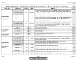
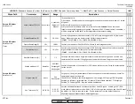
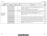
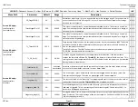
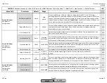
Load of Ignition (O)
0%
0-100%
When
Startmode
is set to "IgnLoadTC", this defines the load at which the burner will be
ignited. If another start mode is selected, parameter has no effect.
x
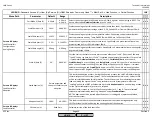
O2InitOffset (O)
0%
-2-2%
For start modes other than standard, this will bias the manipulated variable so that the
transition from lightoff to lowfire can be more rich (negative values) or more lean (positive
values). Offset is in %O2, even 1% gives a substantial offset. Can also be used to shorten the
release to modulation time (by bringing down the measured %O2 to +/- 0.2% faster) for start
modes other than standard.
x
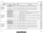
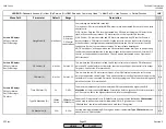
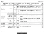
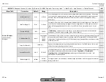
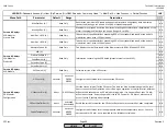
NumberTauSuspend (S)
10
5-140
After burner ignition, the air inside the boiler and stack is slowly replaced with the products
of combustion. Only after this replacement is complete can accurate, representative O2
readings be taken by the O2 sensor. This also determines the low fire waiting time if the
Startmode
is not set to "standard". The value of
NumberTauSuspend
multiplied by
Tau
Low-Fire
determines the time at which representative O2 readings can be taken by the O2
sensor mounted in the stack.
x
Adjust. Temp O2 (U)
Temperature as read by the ambient air temperature sensor when the last point of the O2
control curve was commissioned. Used as the basis for the temperature for the compensated
(TC) start modes.
x
Read Only
Params & Display>
O2Contr/Alarm>
Gas/Oil Settings >
Startmode
SCC Inc.
Page 26
Section 3
HOME
HOME
P - LIST
Summary of Contents for LMV 5 Series
Page 2: ...Intentionally Left Blank ...
Page 41: ...LMV Series Technical Instructions Document No LV5 1000 SCC Inc Page 7 Section 2 HOME ...
Page 42: ...Technical Instructions LMV Series Document No LV5 1000 Section 2 Page 8 SCC Inc HOME ...
Page 43: ...LMV Series Technical Instructions Document No LV5 1000 SCC Inc Page 9 Section 2 HOME ...
Page 44: ...Technical Instructions LMV Series Document No LV5 1000 Section 2 Page 10 SCC Inc HOME ...
Page 45: ...LMV Series Technical Instructions Document No LV5 1000 SCC Inc Page 11 Section 2 HOME ...
Page 46: ...Technical Instructions LMV Series Document No LV5 1000 Section 2 Page 12 SCC Inc HOME ...
Page 47: ...LMV Series Technical Instructions Document No LV5 1000 SCC Inc Page 13 Section 2 HOME ...
Page 48: ...Technical Instructions LMV Series Document No LV5 1000 Section 2 Page 14 SCC Inc HOME ...
Page 49: ...LMV Series Technical Instructions Document No LV5 1000 SCC Inc Page 15 Section 2 HOME ...
Page 50: ...Technical Instructions LMV Series Document No LV5 1000 Section 2 Page 16 SCC Inc HOME ...
Page 51: ...LMV Series Technical Instructions Document No LV5 1000 SCC Inc Page 17 Section 2 HOME ...
Page 52: ...Technical Instructions LMV Series Document No LV5 1000 Section 2 Page 18 SCC Inc HOME ...
Page 53: ...LMV Series Technical Instructions Document No LV5 1000 SCC Inc Page 19 Section 2 HOME ...
Page 54: ...Technical Instructions LMV Series Document No LV5 1000 Section 2 Page 20 SCC Inc HOME ...
Page 55: ...LMV Series Technical Instructions Document No LV5 1000 SCC Inc Page 21 Section 2 HOME ...
Page 373: ...Intentionally Left Blank ...