


LMV Series
Technical Instructions
LV5-1000
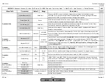
Menu Path
Parameter
Default
Range
Description
51.1
52.2
52.4
LEGEND -
Password Access:
(U)=User, (S)=Service, (O)=OEM, Shaded = Commonly Used, ** = Must Set, X = Has Function, / = Partial Function
LMV
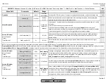
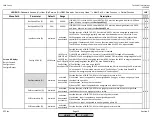
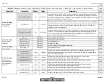
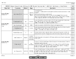
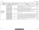
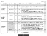
VP_TmeAtmPress (O)
10s
0.2s-63min
If valve proving is activated, this is the time that both the upstream and downstream valves
are closed. If the pressure rises between the valves during this period (enough to open the
N.C. pressure switch), then the upstream valve is leaking and the LMV5 will lockout. A longer
time period will produce a more sensitive test.
x x x
VP_FillTme (O)
3s
0.2-10s
If valve proving is activated, this specifies the time that the upstream valve (V1) is energized,
OUTPUT X9-01.4. This will fill the volume between the main gas valves to line pressure. Note:
If gas valve proving is to be used, opening times of the gas valves must be less than the
maximum value for this parameter.
x x x
VP_Tme_GasPress (O)
10s
0.2s-63min
If valve proving is activated, this is the time that both the upstream and downstream valves
are closed. If the pressure falls between the valves during this period (enough to close the
N.C. pressure switch), then the downstream valve is leaking and the LMV5 will lockout. A
longer time period will produce a more sensitive test.
x x x
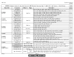
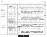
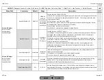
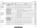
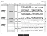
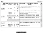
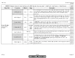
ASN (U)
Product version identification.
x x x
ProductionDate (U)
Date LMV5 unit was produced.
x x x
SerialNumber (U)
Serial number of unit.
x x x
ParamSet Code (U)
Parameter set code.
x x x
ParamSet Vers (U)
Version (revision) of the tagged parameter set.
x x x
Params & Display>
BurnerControl
SW Version (U)
LMV5 software version.
x x x
Read Only
Read Only
Read Only
0 deg
0-90 deg
0-90 deg
0%
0-100%
Params & Display>
BurnerControl>
ProductID
Params & Display
>
RatioControl>
Gas/Oil Settings>
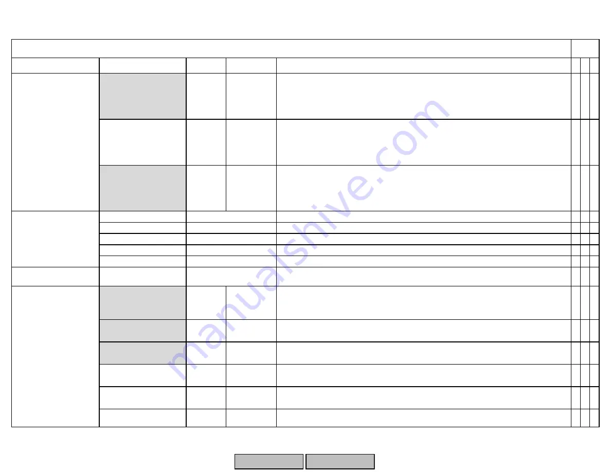
SpecialPositions>
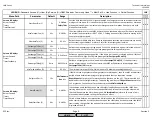
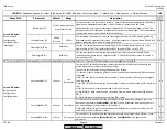
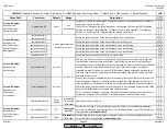
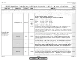
HomePos
HomePosGas or
HomePosOil (S)
Read Only
Read Only
Read Only
Params & Display>
BurnerControl>
ValveProving
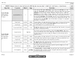
HomePosAux1 (S)
Sets the home position of the aux1 actuator. Each fuel can have its own setting.
Typically set 2 degrees away from closed mechanical stop.
HomePosAux2 (S)
Sets the home position of the aux2 actuator. Each fuel can have its own setting.
Typically set 2 degrees away from closed mechanical stop.
HomePosAux3 (S)
Sets the home position of the aux3 actuator. Each fuel can have its own setting.
Typically set 2 degrees away from closed mechanical stop.
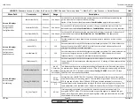
HomePosVSD (S)
Sets the home speed of the VSD. Each fuel can have its own setting.
0 deg
0-90 deg
0 deg
0-90 deg
0 deg
0-90 deg
0 deg
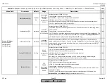
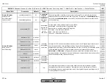
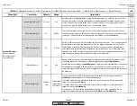
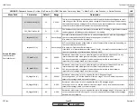
HomePosAir (S)
x x
x
x x x
Sets the home position of the air actuator. Each fuel can have its own setting.
Typically set 2 degrees away from closed mechanical stop.
x x
x
x x
x
x
x x
Sets the home position of the fuel actuator(s). The fuel actuator(s) will also stay in this
position during prepurge. Each fuel can have its own setting. Typically set 2 degrees away
from closed mechanical stop.
SCC Inc.
Page 17
Section 3
HOME
HOME
P - LIST
Summary of Contents for LMV 5 Series
Page 2: ...Intentionally Left Blank ...
Page 41: ...LMV Series Technical Instructions Document No LV5 1000 SCC Inc Page 7 Section 2 HOME ...
Page 42: ...Technical Instructions LMV Series Document No LV5 1000 Section 2 Page 8 SCC Inc HOME ...
Page 43: ...LMV Series Technical Instructions Document No LV5 1000 SCC Inc Page 9 Section 2 HOME ...
Page 44: ...Technical Instructions LMV Series Document No LV5 1000 Section 2 Page 10 SCC Inc HOME ...
Page 45: ...LMV Series Technical Instructions Document No LV5 1000 SCC Inc Page 11 Section 2 HOME ...
Page 46: ...Technical Instructions LMV Series Document No LV5 1000 Section 2 Page 12 SCC Inc HOME ...
Page 47: ...LMV Series Technical Instructions Document No LV5 1000 SCC Inc Page 13 Section 2 HOME ...
Page 48: ...Technical Instructions LMV Series Document No LV5 1000 Section 2 Page 14 SCC Inc HOME ...
Page 49: ...LMV Series Technical Instructions Document No LV5 1000 SCC Inc Page 15 Section 2 HOME ...
Page 50: ...Technical Instructions LMV Series Document No LV5 1000 Section 2 Page 16 SCC Inc HOME ...
Page 51: ...LMV Series Technical Instructions Document No LV5 1000 SCC Inc Page 17 Section 2 HOME ...
Page 52: ...Technical Instructions LMV Series Document No LV5 1000 Section 2 Page 18 SCC Inc HOME ...
Page 53: ...LMV Series Technical Instructions Document No LV5 1000 SCC Inc Page 19 Section 2 HOME ...
Page 54: ...Technical Instructions LMV Series Document No LV5 1000 Section 2 Page 20 SCC Inc HOME ...
Page 55: ...LMV Series Technical Instructions Document No LV5 1000 SCC Inc Page 21 Section 2 HOME ...
Page 373: ...Intentionally Left Blank ...