


LMV Series
Technical Instructions
LV5-1000
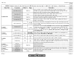
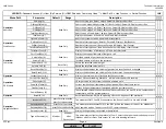
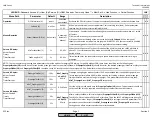
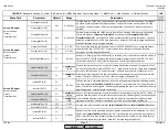
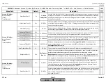
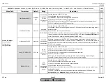
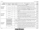
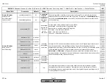
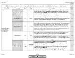
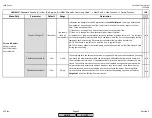
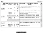
Menu Path
Parameter
Default
Range
Description
51.1
52.2
52.4
LEGEND -
Password Access:
(U)=User, (S)=Service, (O)=OEM, Shaded = Commonly Used, ** = Must Set, X = Has Function, / = Partial Function
LMV
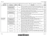
SensExtranlOil (O)
1 Sensor
See Above
For the LMV52, this defines how the combustion chamber will be supervised during the
period when the fuel valves are closed (oil firing).
Options 1 thru 6 as described in parameter
SensExtranlGas
apply to this parameter.
x x
SensPilotPhOil (O)
1 Sensor
See Above
For the LMV52, this defines how the pilot for oil firing is supervised. Options 1 thru 7 as
described in parameters
SensExtranlGas
and
SensPilotPhGas
also apply to this parameter.
x x
SensOperPhOil (O)
1 Sensor
See Above
For the LMV52, this defines how the main flame for oil firing is supervised. Options 1 thru 7
as described in parameters
SensExtranlGas
and
SensPilotPhGas
also apply to this
parameter.
x x
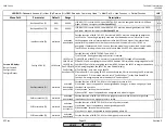
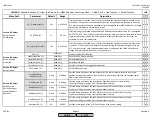
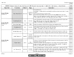
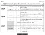
LossOfFlame (S)
1
1-2
Sets the number of times a flame failure is required to cause a lockout. Most US codes
require 1.
x x x
HeavyOil (S)
1
1-16
Sets how many times the LMV5 will attempt to proceed past phase 21 if a start release for
heavy oil is not met on INPUT X6-01.3. After this number of tries a lockout will occur. A
setting of 16 indicates unlimited repetitions.
x x x
StartRelease (S)
1
1-16
Sets how many times the LMV5 will attempt to proceed past phase 21 if a start release is not
met, such as low gas pressure on INPUT terminal X9-03.4. After this number of tries, a
lockout will occur. A setting of 16 indicates unlimited repetitions.
x x x
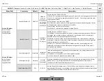
SafetyLoop (S)
1
1-16
Sets how many times the LMV5 will attempt to restart without manual reset when the safety
loop is opened. This parameter should always be set to 1. A setting of 16 indicates unlimited
repetitions.
x x x
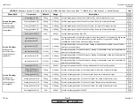
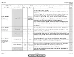
ValveProvingType (O)
No VP
No VP
VP startup
VP shutdown
VP stup/shd
This determines if gas valve proving (leak testing) will be performed. Gas valve proving can
be performed on startup, shutdown, or both. If 'No VP' is selected, valve proving will not be
performed. If 'No VP' is selected, and parameter
Config_PS-VP/CPI
is set to PS-VP, then
INPUT X9-03.2 is essentially deactivated.
x x x
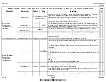
Config_PS-VP/CPI (O)
PS-VP
PS-VP
CPI Gas
CPI Gas+Oil CPI
Oil
Sets the function of INPUT X9-03.2. Functions: PS-VP (Pressure Switch - Valve Proving) for
use with automatic valve proving, proof of closure (POC) for gas valves, POC for oil valves, or
POC for gas and oil valves. Note: POC and CPI (Closed Position Indication) are the same
function. Input can be deactivated by setting to PS-VP and de-activating valve proving. The
same parameter is also available under :
Params & Display > BurnerControl > Configuration
x x x
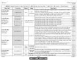
VP_EvacTme (O)
3s
0.2-10s
If valve proving is activated, this specifies the time that the downstream valve (V2) is
energized, OUTPUT X9-01.3. This will evacuate any gas that might exist between the gas
valves. Note: If gas valve proving is used, opening times of the gas valves must be less than
the maximum value for this parameter.
x x x
Params & Display>
BurnerControl>
Configuration>
ConfigFlameDet
Params & Display>
BurnerControl>
ValveProving
Params & Display
>
BurnerControl>
Configuration>
RepetitCounter
SCC Inc.
Page 16
Section 3
HOME
HOME
P - LIST
Summary of Contents for LMV 5 Series
Page 2: ...Intentionally Left Blank ...
Page 41: ...LMV Series Technical Instructions Document No LV5 1000 SCC Inc Page 7 Section 2 HOME ...
Page 42: ...Technical Instructions LMV Series Document No LV5 1000 Section 2 Page 8 SCC Inc HOME ...
Page 43: ...LMV Series Technical Instructions Document No LV5 1000 SCC Inc Page 9 Section 2 HOME ...
Page 44: ...Technical Instructions LMV Series Document No LV5 1000 Section 2 Page 10 SCC Inc HOME ...
Page 45: ...LMV Series Technical Instructions Document No LV5 1000 SCC Inc Page 11 Section 2 HOME ...
Page 46: ...Technical Instructions LMV Series Document No LV5 1000 Section 2 Page 12 SCC Inc HOME ...
Page 47: ...LMV Series Technical Instructions Document No LV5 1000 SCC Inc Page 13 Section 2 HOME ...
Page 48: ...Technical Instructions LMV Series Document No LV5 1000 Section 2 Page 14 SCC Inc HOME ...
Page 49: ...LMV Series Technical Instructions Document No LV5 1000 SCC Inc Page 15 Section 2 HOME ...
Page 50: ...Technical Instructions LMV Series Document No LV5 1000 Section 2 Page 16 SCC Inc HOME ...
Page 51: ...LMV Series Technical Instructions Document No LV5 1000 SCC Inc Page 17 Section 2 HOME ...
Page 52: ...Technical Instructions LMV Series Document No LV5 1000 Section 2 Page 18 SCC Inc HOME ...
Page 53: ...LMV Series Technical Instructions Document No LV5 1000 SCC Inc Page 19 Section 2 HOME ...
Page 54: ...Technical Instructions LMV Series Document No LV5 1000 Section 2 Page 20 SCC Inc HOME ...
Page 55: ...LMV Series Technical Instructions Document No LV5 1000 SCC Inc Page 21 Section 2 HOME ...
Page 373: ...Intentionally Left Blank ...