


LMV Series
Technical Instructions
LV5-1000
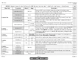
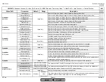
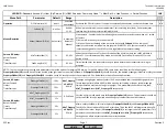
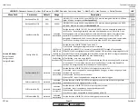
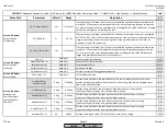
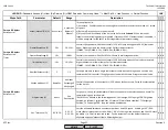
Menu Path
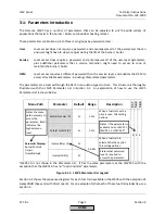
Parameter
Default
Range
Description
51.1
52.2
52.4
LEGEND -
Password Access:
(U)=User, (S)=Service, (O)=OEM, Shaded = Commonly Used, ** = Must Set, X = Has Function, / = Partial Function
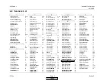
LMV
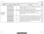
StartReleaseGas (O)
StartRel
Gas
deactivated
StartRelGas
CPI Gas
CPI Gas+Oil
CPI Oil
Sets the function of INPUT X7-03.2.
1) deactivated - terminal has no function.
2) StartRelGas - input must be energized in phase 21-62.
3) CPI Gas - proof of closure (POC) for gas valves.
4) CPI Gas+Oil - proof of closure (POC) for gas and oil valves wired on the same terminal.
5) CPI Oil - proof of closure (POC) for oil valves.
x x x
StartReleaseOil (O)
activated
activated
deactivated
HT/FG-RedCo
Sets the function of INPUT X6-01.1.
1) activated - input must be energized in phase 21-62, typically used for an atomizing media
pressure switch.
2) deactivated - terminal has no function.
3) HT/FG-RedCo - input for a redundant contact when using an external flame safeguard. This
input is inverse of the main contact on terminal X6-01.3. See parameter
HeavyOilDirStart
for
more information on external flame safeguards (LMV52 only).
/ x x
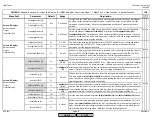
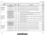
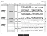
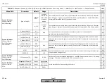
AirPressureTest (O)
activated
activated
deactivated
deactInStby
Activates or deactivates INPUT X3-02.1, the combustion air pressure switch. Activate for
forced or induced draft burners. Can also be set to "deactInStby", so that the status of the air
pressure switch is not evaluated in standby. However, the burner will not start until INPUT
X3-02.1 is de-energized.
x x x
Config_PS-VP/CPI (O)
CPI Gas
PS-VP
CPI Gas
CPI Gas+Oil
CPI Oil
Sets the function of INPUT X9-03.2.
1) PS-VP - pressure switch for use with automatic valve proving.
2) CPI Gas - proof of closure (POC) for gas valves.
3) CPI Gas+Oil - POC for gas and oil valves on the same terminal.
4) CPI Oil - POC for oil valves.
Note: Input can be deactivated by setting to PS-VP and de-activating valve proving at:
Params & Display > BurnerControl > ValveProving > ValveProvingType
x x x
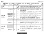
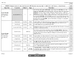
FGR-PS/FCC (O)
FCC
FCC
FGR-PS
deactivated
PSdeactStby
PS VSD
Sets the function of INPUT X4-01.3.
1) FCC - checks the status of the fan motor starter.
2) FGR-PS - checks the status of an FGR pressure switch.
3) deactivated - terminal has no function.
4) PSdeactStby - checks the status of an FGR pressure switch but the pressure switch is not
evaluated in standby.
5) PS VSD - checks the status of a second air pressure switch based on VSD speed. See
RotSpeed PS on
and
RotSpeed PS off
(not available on LMV51.1).
/ x x
Params & Display>
BurnerControl>
Configuration>
ConfigIn/Output
SCC Inc.
Page 12
Section 3
HOME
HOME
P - LIST
Summary of Contents for LMV 5 Series
Page 2: ...Intentionally Left Blank ...
Page 41: ...LMV Series Technical Instructions Document No LV5 1000 SCC Inc Page 7 Section 2 HOME ...
Page 42: ...Technical Instructions LMV Series Document No LV5 1000 Section 2 Page 8 SCC Inc HOME ...
Page 43: ...LMV Series Technical Instructions Document No LV5 1000 SCC Inc Page 9 Section 2 HOME ...
Page 44: ...Technical Instructions LMV Series Document No LV5 1000 Section 2 Page 10 SCC Inc HOME ...
Page 45: ...LMV Series Technical Instructions Document No LV5 1000 SCC Inc Page 11 Section 2 HOME ...
Page 46: ...Technical Instructions LMV Series Document No LV5 1000 Section 2 Page 12 SCC Inc HOME ...
Page 47: ...LMV Series Technical Instructions Document No LV5 1000 SCC Inc Page 13 Section 2 HOME ...
Page 48: ...Technical Instructions LMV Series Document No LV5 1000 Section 2 Page 14 SCC Inc HOME ...
Page 49: ...LMV Series Technical Instructions Document No LV5 1000 SCC Inc Page 15 Section 2 HOME ...
Page 50: ...Technical Instructions LMV Series Document No LV5 1000 Section 2 Page 16 SCC Inc HOME ...
Page 51: ...LMV Series Technical Instructions Document No LV5 1000 SCC Inc Page 17 Section 2 HOME ...
Page 52: ...Technical Instructions LMV Series Document No LV5 1000 Section 2 Page 18 SCC Inc HOME ...
Page 53: ...LMV Series Technical Instructions Document No LV5 1000 SCC Inc Page 19 Section 2 HOME ...
Page 54: ...Technical Instructions LMV Series Document No LV5 1000 Section 2 Page 20 SCC Inc HOME ...
Page 55: ...LMV Series Technical Instructions Document No LV5 1000 SCC Inc Page 21 Section 2 HOME ...
Page 373: ...Intentionally Left Blank ...