


LMV Series
Technical Instructions
LV5-1000
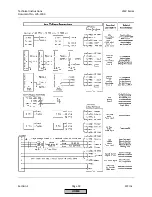
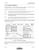
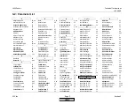
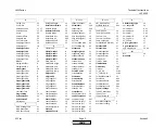
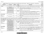
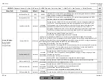
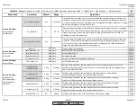
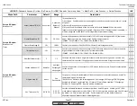
Menu Path
Parameter
Default
Range
Description
51.1
52.2
52.4
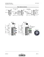
LEGEND -
Password Access:
(U)=User, (S)=Service, (O)=OEM, Shaded = Commonly Used, ** = Must Set, X = Has Function, / = Partial Function
LMV
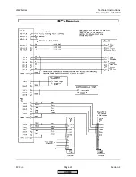
PrepurgePt1Gas (S)
PrepurgePt1Oil (S)
PrepurgePt3Gas (S)
PrepurgePt3Oil (S)
PreIgnitionTGas (S)
2s
0.2- 63s
PreIgnitionTOil (S)
2s
0.2- 44s
MinOnTmeOilPump (S)
5s
0.2-63s
When LO w Gasp (Light Oil with Gas pilot) is selected, this is the minimum time the oil pump
can run (OUTPUT X6-02.3) before the LMV5 attempts to light the pilot, (OUTPUT X9-01.2).
Time starts in phase 22, and will hold in phase 36 until this parameter times out.
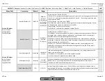
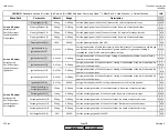
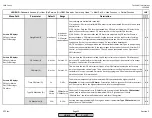
SafetyTme1Gas (O)
5s
1-
MaxSafety
TGas
SafetyTme1Oil (O)
5s
1-
MaxSafety
TOil
Interval1Gas (S)
2s
Interval1Oil (S)
2s
SafetyTme2Gas (O)
5s
1-
MaxSafety
TGas
SafetyTme2Oil (O)
5s
1-
MaxSafety
TOil
MaxSafetyTGas (O)
10s
1-10s
MaxSafetyTOil (O)
15s
1-15s
Interval2Gas (S)
2s
Interval2Oil (S)
2s
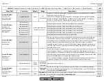
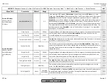
x x
x x x
x
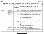
Sets the minimum time the LMV5 stays in phase 34 on startups after a normal shutdown.
Time will be longer if
PrepurgeTmeGas(Oil)
is set larger than
PrepurgePt1Gas(Oil)
+
PrepurgePt3Gas(Oil)
. Setting has no effect on startups after a safety shutdown. If an Aux3
actuator is used, phase 34 is the time when the air actuator / VSD are at purge position and
the Aux3 actuator is also at purge position.
This defines the time the ignition transformer (OUTPUT X4-02.3) alone is energized before
the pilot valve (OUTPUT X9-01.2) or main valves (for direct spark fuel trains) become
energized. Sets the length of phase 38.
0.2s-63min
0.2s-63min
0.2s
0.2s
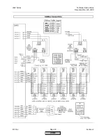
Params & Display>
BurnerControl>
Times>
TimesStartup1
Params & Display>
BurnerControl>
Times>
TimesStartup1
0.2-63s
0.2-630s
Params & Display>
BurnerControl>
Times>
TimesStartup2
Sets the maximum allowable time for
SafetyTme1Gas(Oil)
and
SafetyTme2Gas(Oil)
above.
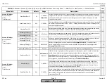
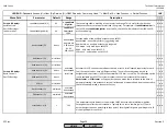
x
When a fuel train with a pilot is used, this defines the overlap of the pilot (OUTPUT X9-01.2)
and the main fuel valves. After this time expires the pilot is de-energized if continuous pilot
is not selected. Shorter times are more safe. No effect for fuel trains having direct spark
ignition of main fuel. This time is also known as TSA2. Sets the length of phase 50.
Defines the main flame stabilizing period at ignition position before modulation. This time
begins after
SafetyTme2Gas(Oil)
expires. During this period, only the main fuel valves are
open. The pilot valve is de-energized unless continuous pilot is selected. No effect for fuel
trains having direct spark ignition of main fuel. Sets the length of phase 52.
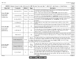
Sets the time the LMV5 stays in phase 30 on startups after a normal shutdown. Setting has
no effect on startups after a safety shutdown. If an Aux3 actuator is used, phase 30 is the
time when the air actuator / VSD are at purge position and the Aux3 actuator is at home
position.
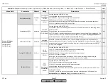
When a fuel train with a pilot is used, this setting defines the overlap of the spark (OUTPUT
X4-02.3) and the pilot valve (OUTPUT X9-01.2). After this time expires, spark is de-energized
but the PV remains open if a flame is present. If a flame is not sensed, a lockout occurs. If
directly spark igniting the main fuel, this defines the overlap of the spark and the main fuel
valves. This time is also known as TSA1. Sets the length of phases 40-42.
When a fuel train is selected that has a pilot, this setting defines the pilot stabilizing period.
This time begins after
SafetyTme1Gas(Oil
) expires. During this period, only the pilot valve is
open. The spark is de-energized. If directly spark igniting the main fuel, this defines the main
stabilizing period. Sets the length of phase 44.
x x
SCC Inc.
Page 8
Section 3
HOME
HOME
P - LIST
Summary of Contents for LMV 5 Series
Page 2: ...Intentionally Left Blank ...
Page 41: ...LMV Series Technical Instructions Document No LV5 1000 SCC Inc Page 7 Section 2 HOME ...
Page 42: ...Technical Instructions LMV Series Document No LV5 1000 Section 2 Page 8 SCC Inc HOME ...
Page 43: ...LMV Series Technical Instructions Document No LV5 1000 SCC Inc Page 9 Section 2 HOME ...
Page 44: ...Technical Instructions LMV Series Document No LV5 1000 Section 2 Page 10 SCC Inc HOME ...
Page 45: ...LMV Series Technical Instructions Document No LV5 1000 SCC Inc Page 11 Section 2 HOME ...
Page 46: ...Technical Instructions LMV Series Document No LV5 1000 Section 2 Page 12 SCC Inc HOME ...
Page 47: ...LMV Series Technical Instructions Document No LV5 1000 SCC Inc Page 13 Section 2 HOME ...
Page 48: ...Technical Instructions LMV Series Document No LV5 1000 Section 2 Page 14 SCC Inc HOME ...
Page 49: ...LMV Series Technical Instructions Document No LV5 1000 SCC Inc Page 15 Section 2 HOME ...
Page 50: ...Technical Instructions LMV Series Document No LV5 1000 Section 2 Page 16 SCC Inc HOME ...
Page 51: ...LMV Series Technical Instructions Document No LV5 1000 SCC Inc Page 17 Section 2 HOME ...
Page 52: ...Technical Instructions LMV Series Document No LV5 1000 Section 2 Page 18 SCC Inc HOME ...
Page 53: ...LMV Series Technical Instructions Document No LV5 1000 SCC Inc Page 19 Section 2 HOME ...
Page 54: ...Technical Instructions LMV Series Document No LV5 1000 Section 2 Page 20 SCC Inc HOME ...
Page 55: ...LMV Series Technical Instructions Document No LV5 1000 SCC Inc Page 21 Section 2 HOME ...
Page 373: ...Intentionally Left Blank ...