


LMV Series
Technical Instructions
LV5-1000
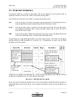
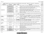
Menu Path
Parameter
Default
Range
Description
51.1
52.2
52.4
LEGEND -
Password Access:
(U)=User, (S)=Service, (O)=OEM, Shaded = Commonly Used, ** = Must Set, X = Has Function, / = Partial Function
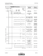
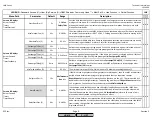
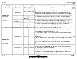
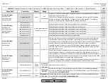
LMV
GasFiring (U)
Hours run firing gas. Reset / adjust:
Params & Display > HoursRun
OilStage1/Mod (U)
Hours run on modulating or stage 1 oil. Reset / adjust:
Params & Display > HoursRun
OilStage2 (U)
Hours run on stage 2 oil. Reset / adjust at:
Params & Display > HoursRun
OilStage3 (U)
Hours run on stage 3 oil. Reset / adjust at:
Params & Display > HoursRun
TotalHoursReset (U)
Hours run on all fuels. Reset / adjust:
Params & Display > HoursRun
TotalHours (U)
Displays the number of hours run on all fuels. Not resettable.
SystemOnPower (U)
Hours the system has been powered. Not resettable.
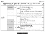
GasStartCount (U)
Number of startups on gas. Reset at:
Params & Display > StartCounter
OilStartCount (U)
Number of startups on oil. Reset at:
Params & Display > StartCounter
TotalStartCountR (U)
Number of startups on all fuels. Reset at:
Params & Display > StartCounter
TotalStartCount (U)
Displays the number of startups on all fuels. Not resettable.
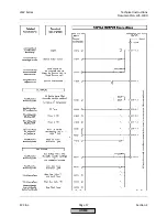
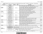
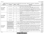
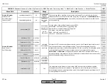
Curr Flow Rate (U)
Displays the current flow rate of fuel, gas or oil.
Volume Gas (U)
Totalized volume of gas since the last reset.
Volume Oil (U)
Totalized volume of oil since the last reset.
Volume Gas R (U)
Resets the totalized volume of gas.
Volume Oil R (U)
Resets the totalized volume of oil.
Reset Date Gas (U)
Displays the date when the volume of gas was last reset. Cannot be changed.
Reset Date Oil (U)
Displays the date when the volume of oil was last reset. Cannot be changed.
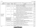
Operation
LockoutCounter (U)
Displays the total number of lockouts that have occurred.
x x x
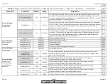
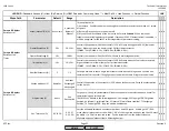
Current O2 Value (U)
Current O2 sensor reading. Wet basis - will be lower than dry O2 reading.
O2 Setpoint (U)
O2 target value for the current load can be viewed here.
SupplyAirTemp (U)
Current combustion air temperature if equipped with ambient temp sensor.
FlueGasTemp (U)
Current flue gas temperature if equipped with flue gas temp sensor.
CombEfficiency (U)
The calculated value of the combustion efficiency based on the wet O2 value, combustion air
temperature, and flue gas temperature.
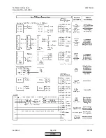
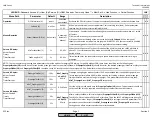
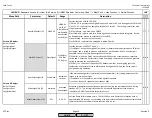
Operation
BurnerID (U)
Burner identification. Adjust at:
Updating > BurnerID
(requires OEM password)
x x x
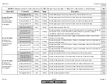
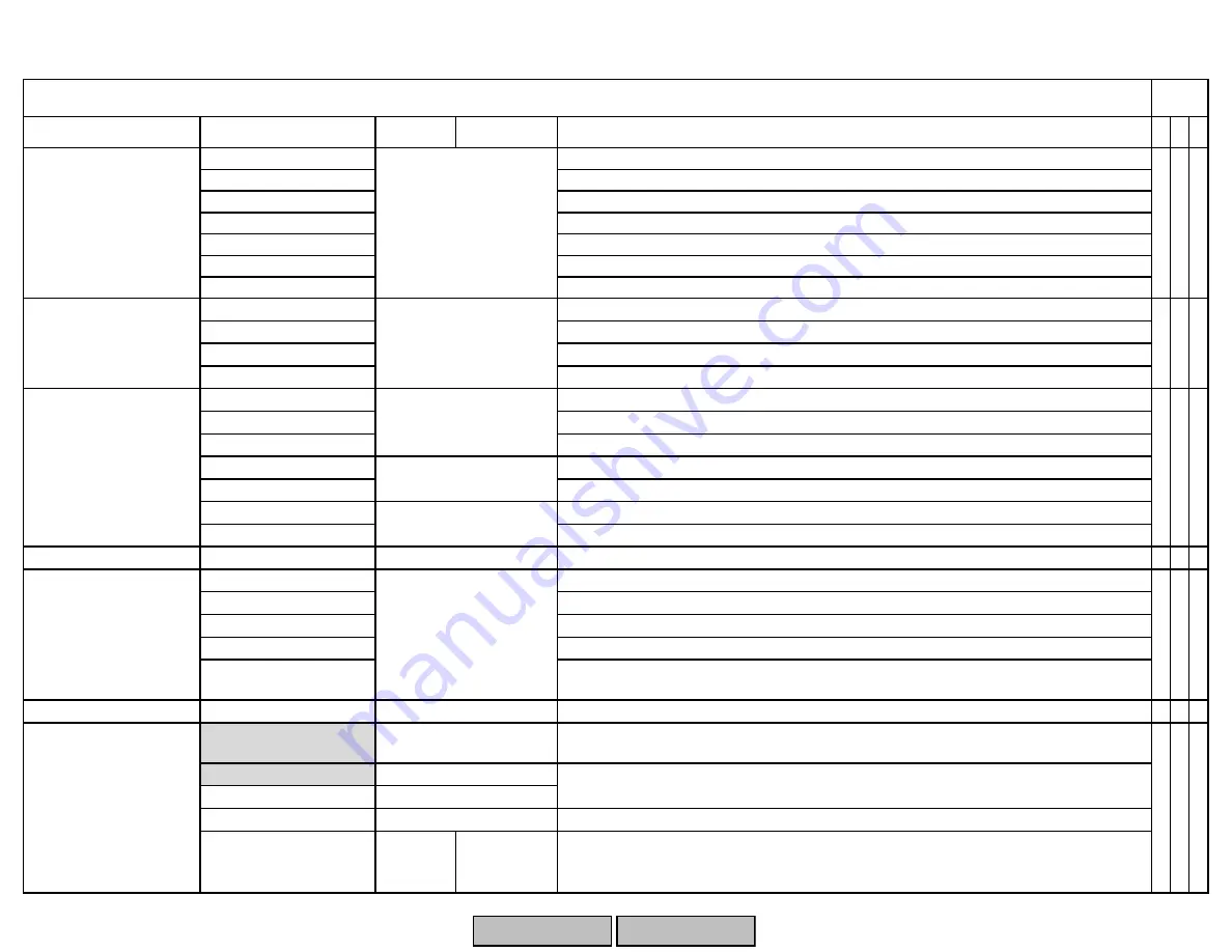
InterfacePC (U)
This activates COM 1, the DB9 connector on the front of the AZL to use with ACS450.
GatewayBASon (U)
GatewayBASoff (U)
Gateway status (U)
Displays if the gateway is activated or deactivated.
Type of Gateway (U)
Modbus
Modbus
eBus
Data output
This parameter configures the protocol of Com 2. Select the proper communication protocol
(Modbus, eBUS) or select 'Data output' for use with trending software.
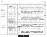
Operation>
HoursRun
Operation>
StartCounter
Operation
>
Fuel Meter
Operation>
O2 Module
Operation
>
OptgModeSelect
Read Only
x x x
Read Only
x x x
Read Only
Reset Only
x x
x x
press Enter to activate
Read Only
Read Only
Read Only
Read Only
Read Only
press Enter to activate,
press Esc to deactivate
This activates or deactivates COM 2, the RJ45 jack on the bottom of the AZL, for Modbus or
eBUS communication. This port uses RS-232 communications.
press Enter to deactivate
x x x
SCC Inc.
Page 6
Section 3
HOME
HOME
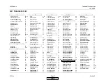
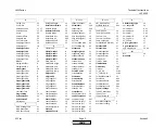
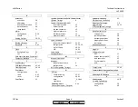
P - LIST
Summary of Contents for LMV 5 Series
Page 2: ...Intentionally Left Blank ...
Page 41: ...LMV Series Technical Instructions Document No LV5 1000 SCC Inc Page 7 Section 2 HOME ...
Page 42: ...Technical Instructions LMV Series Document No LV5 1000 Section 2 Page 8 SCC Inc HOME ...
Page 43: ...LMV Series Technical Instructions Document No LV5 1000 SCC Inc Page 9 Section 2 HOME ...
Page 44: ...Technical Instructions LMV Series Document No LV5 1000 Section 2 Page 10 SCC Inc HOME ...
Page 45: ...LMV Series Technical Instructions Document No LV5 1000 SCC Inc Page 11 Section 2 HOME ...
Page 46: ...Technical Instructions LMV Series Document No LV5 1000 Section 2 Page 12 SCC Inc HOME ...
Page 47: ...LMV Series Technical Instructions Document No LV5 1000 SCC Inc Page 13 Section 2 HOME ...
Page 48: ...Technical Instructions LMV Series Document No LV5 1000 Section 2 Page 14 SCC Inc HOME ...
Page 49: ...LMV Series Technical Instructions Document No LV5 1000 SCC Inc Page 15 Section 2 HOME ...
Page 50: ...Technical Instructions LMV Series Document No LV5 1000 Section 2 Page 16 SCC Inc HOME ...
Page 51: ...LMV Series Technical Instructions Document No LV5 1000 SCC Inc Page 17 Section 2 HOME ...
Page 52: ...Technical Instructions LMV Series Document No LV5 1000 Section 2 Page 18 SCC Inc HOME ...
Page 53: ...LMV Series Technical Instructions Document No LV5 1000 SCC Inc Page 19 Section 2 HOME ...
Page 54: ...Technical Instructions LMV Series Document No LV5 1000 Section 2 Page 20 SCC Inc HOME ...
Page 55: ...LMV Series Technical Instructions Document No LV5 1000 SCC Inc Page 21 Section 2 HOME ...
Page 373: ...Intentionally Left Blank ...