


Technical Instructions
LMV Series
Document No. LV5-8000
Appendix A
Page 34
SCC Inc.
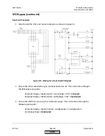
Remote Setpoint (continued)
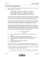
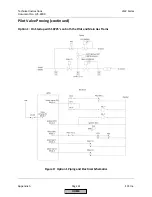
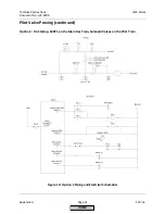
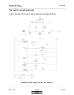
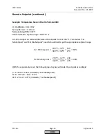
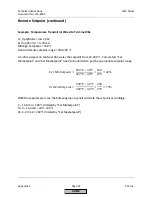
Example: Temperature Transmitter Wired to Terminal X61
LC_OptgMode = IntLC X62
Ext Inp X62 U/I = 4..20 mA
MRange TempSens = 300 °F
Desired remote setpoint range = 200-240 °F
A 4-20 mA signal on terminal X62 scales the setpoint from 32-300 °F. Parameters “Ext
MinSetpoint” and “Ext MaxSetpoint” need to be utilized to get the appropriate setpoint range.
=
200℉ − 32℉
302℉ − 32℉
=
168
270
= 62%
=
240℉ − 32℉
302℉ − 32℉
=
208
270
= 77%
With these parameters set, the following input signals will scale the setpoint accordingly:
4 – 13.9 mA = 200 °F (limited by “Ext MinSetpoint”)
13.9 – 16.3 mA = 200 - 240 °F
16.3 - 20 mA = 240 °F (limited by “Ext MaxSetpoint”)
HOME
Summary of Contents for LMV 5 Series
Page 2: ...Intentionally Left Blank ...
Page 41: ...LMV Series Technical Instructions Document No LV5 1000 SCC Inc Page 7 Section 2 HOME ...
Page 42: ...Technical Instructions LMV Series Document No LV5 1000 Section 2 Page 8 SCC Inc HOME ...
Page 43: ...LMV Series Technical Instructions Document No LV5 1000 SCC Inc Page 9 Section 2 HOME ...
Page 44: ...Technical Instructions LMV Series Document No LV5 1000 Section 2 Page 10 SCC Inc HOME ...
Page 45: ...LMV Series Technical Instructions Document No LV5 1000 SCC Inc Page 11 Section 2 HOME ...
Page 46: ...Technical Instructions LMV Series Document No LV5 1000 Section 2 Page 12 SCC Inc HOME ...
Page 47: ...LMV Series Technical Instructions Document No LV5 1000 SCC Inc Page 13 Section 2 HOME ...
Page 48: ...Technical Instructions LMV Series Document No LV5 1000 Section 2 Page 14 SCC Inc HOME ...
Page 49: ...LMV Series Technical Instructions Document No LV5 1000 SCC Inc Page 15 Section 2 HOME ...
Page 50: ...Technical Instructions LMV Series Document No LV5 1000 Section 2 Page 16 SCC Inc HOME ...
Page 51: ...LMV Series Technical Instructions Document No LV5 1000 SCC Inc Page 17 Section 2 HOME ...
Page 52: ...Technical Instructions LMV Series Document No LV5 1000 Section 2 Page 18 SCC Inc HOME ...
Page 53: ...LMV Series Technical Instructions Document No LV5 1000 SCC Inc Page 19 Section 2 HOME ...
Page 54: ...Technical Instructions LMV Series Document No LV5 1000 Section 2 Page 20 SCC Inc HOME ...
Page 55: ...LMV Series Technical Instructions Document No LV5 1000 SCC Inc Page 21 Section 2 HOME ...
Page 373: ...Intentionally Left Blank ...