

LMV Series
Technical Instructions
Document No. LV5-8000
SCC Inc.
Page 23
Appendix A
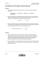
Pilot Valve Proving (continued)
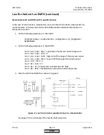
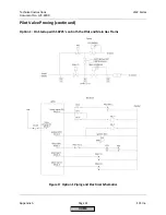
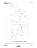
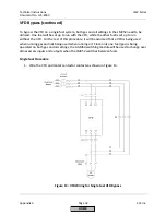
Option 1 Sequence of Operation
1.
The LMV5 is in standby. All valves are closed and all relay contacts are as shown in the
electrical schematic.
2.
The LMV5 receives a call for heat. The SV terminal (X9-01.1) energizes before the
blower, energizing the PVLT (Pilot Valve Leak Test). The PVLT opens, and connects the
volumes between the pilot valves and main valves. The PVLT POC switch also opens,
preventing the operation of the pilot valves.
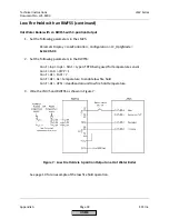
3.
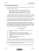
During prepurge, the main valve proving sequence takes place as normal. The PS-VP
(Pressure Switch - Valve Proving) is wired to terminal X9-03.2 as normal. The setpoint of
the PS-VP should be set for half of the inlet pressure.
4.
The LMV5 drives to ignition position. The ignition transformer output (X4-02.3)
energizes, thereby energizing the CR-2 coil, and latching the CR-1 coil from the power
supplied from X9-01.1. At the same time, one of the CR-1 contacts opens, thereby
closing the PVLT valve and closing the PVLT POC switch. Note that the PVLT POC switch
must be closed before the pilot valves open.
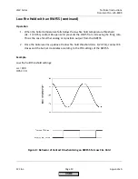
5.
The LMV5 continues light off and runs as normal, with the CR-1 coil latched in and the
PVLT valve closed.
6.
Upon shutdown, the SV terminal (X9-01.1) de-energizes, which un-latches the circuit.
The PVLT valve remains closed until the next start up.
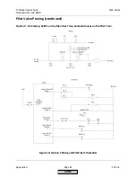
Option 1 Important Notes
1.
The proof of closure switch on the PVLT ensures that gas is unable to flow between the
pilot and main valves before the pilot attempts to light.
2.
All four valves are tested at the inlet pressure, which is the pressure that they normally
operate at. The PS-VP should be set for half of the inlet pressure which provides a valid
test for all four valves.
3.
Valve proving must be done on startup only.
HOME
Summary of Contents for LMV 5 Series
Page 2: ...Intentionally Left Blank ...
Page 41: ...LMV Series Technical Instructions Document No LV5 1000 SCC Inc Page 7 Section 2 HOME ...
Page 42: ...Technical Instructions LMV Series Document No LV5 1000 Section 2 Page 8 SCC Inc HOME ...
Page 43: ...LMV Series Technical Instructions Document No LV5 1000 SCC Inc Page 9 Section 2 HOME ...
Page 44: ...Technical Instructions LMV Series Document No LV5 1000 Section 2 Page 10 SCC Inc HOME ...
Page 45: ...LMV Series Technical Instructions Document No LV5 1000 SCC Inc Page 11 Section 2 HOME ...
Page 46: ...Technical Instructions LMV Series Document No LV5 1000 Section 2 Page 12 SCC Inc HOME ...
Page 47: ...LMV Series Technical Instructions Document No LV5 1000 SCC Inc Page 13 Section 2 HOME ...
Page 48: ...Technical Instructions LMV Series Document No LV5 1000 Section 2 Page 14 SCC Inc HOME ...
Page 49: ...LMV Series Technical Instructions Document No LV5 1000 SCC Inc Page 15 Section 2 HOME ...
Page 50: ...Technical Instructions LMV Series Document No LV5 1000 Section 2 Page 16 SCC Inc HOME ...
Page 51: ...LMV Series Technical Instructions Document No LV5 1000 SCC Inc Page 17 Section 2 HOME ...
Page 52: ...Technical Instructions LMV Series Document No LV5 1000 Section 2 Page 18 SCC Inc HOME ...
Page 53: ...LMV Series Technical Instructions Document No LV5 1000 SCC Inc Page 19 Section 2 HOME ...
Page 54: ...Technical Instructions LMV Series Document No LV5 1000 Section 2 Page 20 SCC Inc HOME ...
Page 55: ...LMV Series Technical Instructions Document No LV5 1000 SCC Inc Page 21 Section 2 HOME ...
Page 373: ...Intentionally Left Blank ...