

LMV Series
Technical Instructions
Document No. LV5-8000
SCC Inc.
Page 13
Appendix A
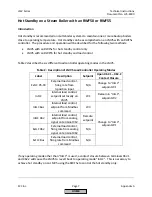
Hot Standby with a Temperature Switch (continued)
Procedure
1.
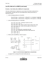
Set the LMV5 for load control operating mode “ExtLC X5-03” through the following
menu path:
Params & Display > LoadController > Configuration > LC_OptgMode =
ExtLC X5-03
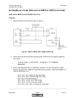
2.
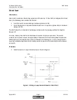
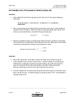
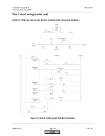
Wire a jumper between terminals X5-03.4 and X5-03.2 on the LMV5. Terminal X5-03.4
outputs 120 Vac at all times. When the LMV5 is in operating mode “ExtLC X5-03” and
120 Vac is on terminal X5-03.2, the LMV5’s firing rate decreases.
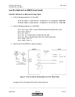
3.
Wire the temperature switch contact between terminals X62.1 and X62.2 on the LMV5.
This needs to be a normally-open contact that closes once the temperature of the boiler
rises above the temperature setting on the temperature switch.
Operation
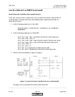
1.
When the temperature of the boiler is below the temperature switch setting, the
contact between X62.1 and X62.2 will be open. The LMV5 will be in operating mode
“ExtLC X5-03”, waiting for a 3-position input for its firing rate command. Since line
power from terminal X5-03.4 has been directly connected to the terminal that
decreases the firing rate (X5-03.2), the LMV5 will remain at low fire.
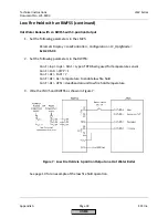
2.
Once the temperature rises above the temperature switch setting, the contact between
X62.1 and X62.2 closes. The LMV5 changes to operating mode “IntLC” and modulates to
maintain setpoint W1.
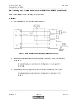
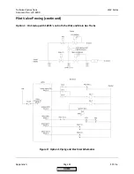
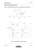
X5-03.4
X5-03.2
Temperature switch contact
X62.2
X62.1
HOME
Summary of Contents for LMV 5 Series
Page 2: ...Intentionally Left Blank ...
Page 41: ...LMV Series Technical Instructions Document No LV5 1000 SCC Inc Page 7 Section 2 HOME ...
Page 42: ...Technical Instructions LMV Series Document No LV5 1000 Section 2 Page 8 SCC Inc HOME ...
Page 43: ...LMV Series Technical Instructions Document No LV5 1000 SCC Inc Page 9 Section 2 HOME ...
Page 44: ...Technical Instructions LMV Series Document No LV5 1000 Section 2 Page 10 SCC Inc HOME ...
Page 45: ...LMV Series Technical Instructions Document No LV5 1000 SCC Inc Page 11 Section 2 HOME ...
Page 46: ...Technical Instructions LMV Series Document No LV5 1000 Section 2 Page 12 SCC Inc HOME ...
Page 47: ...LMV Series Technical Instructions Document No LV5 1000 SCC Inc Page 13 Section 2 HOME ...
Page 48: ...Technical Instructions LMV Series Document No LV5 1000 Section 2 Page 14 SCC Inc HOME ...
Page 49: ...LMV Series Technical Instructions Document No LV5 1000 SCC Inc Page 15 Section 2 HOME ...
Page 50: ...Technical Instructions LMV Series Document No LV5 1000 Section 2 Page 16 SCC Inc HOME ...
Page 51: ...LMV Series Technical Instructions Document No LV5 1000 SCC Inc Page 17 Section 2 HOME ...
Page 52: ...Technical Instructions LMV Series Document No LV5 1000 Section 2 Page 18 SCC Inc HOME ...
Page 53: ...LMV Series Technical Instructions Document No LV5 1000 SCC Inc Page 19 Section 2 HOME ...
Page 54: ...Technical Instructions LMV Series Document No LV5 1000 Section 2 Page 20 SCC Inc HOME ...
Page 55: ...LMV Series Technical Instructions Document No LV5 1000 SCC Inc Page 21 Section 2 HOME ...
Page 373: ...Intentionally Left Blank ...