
Technical Instructions
LMV Series
Document No. LV5-8000
Appendix A
Page 12
SCC Inc.
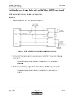
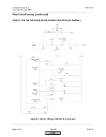
Hot Standby with a Temperature Switch
Introduction
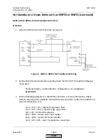
Hot standby is recommended on multi-boiler systems to maintain one or more backup boilers
close to operating temperature. A simple hot standby with an LMV5 is accomplished through
the use of a temperature switch. A temperature switch closes a contact which allows the
burner to release to modulation and exit hot standby mode. With proper wiring and parameter
setup, this simple device will create an effective hot standby with an LMV5 controller.
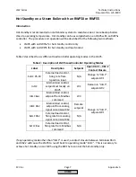
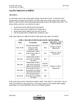
Table 3 describes the six different load controller operating modes in the LMV5.
Table 3: Description of LMV5 Load Controller Operating Modes
Label
Description
Setpoint
Upon X62.1 – X62.2
Contact Closure
ExtLC X5-03
External load control,
firing rate from
3-position input
N/A
Change to “IntLC”,
setpoint W1
IntLC
Internal load control,
setpoint set locally on
LMV5
W1
Remain in “IntLC”,
setpoint W2
IntLC Bus
Internal load control,
setpoint from Modbus
command
W3
Change to “IntLC”,
setpoint W1
IntLC X62
Internal load control,
setpoint from analog
signal on terminal X62
Remote
setpoint
ExtLC X62
External load control,
firing rate from analog
signal on terminal X62
N/A
ExtLC Bus
External load control,
firing rate from Modbus
command
N/A
If any operating mode other than “IntLC” is used, a contact closure between terminals X62.1
and X62.2 will cause the LMV5 to revert back to operating mode “IntLC”. This concept is
necessary to achieve a hot standby with a temperature switch.
HOME
Summary of Contents for LMV 5 Series
Page 2: ...Intentionally Left Blank ...
Page 41: ...LMV Series Technical Instructions Document No LV5 1000 SCC Inc Page 7 Section 2 HOME ...
Page 42: ...Technical Instructions LMV Series Document No LV5 1000 Section 2 Page 8 SCC Inc HOME ...
Page 43: ...LMV Series Technical Instructions Document No LV5 1000 SCC Inc Page 9 Section 2 HOME ...
Page 44: ...Technical Instructions LMV Series Document No LV5 1000 Section 2 Page 10 SCC Inc HOME ...
Page 45: ...LMV Series Technical Instructions Document No LV5 1000 SCC Inc Page 11 Section 2 HOME ...
Page 46: ...Technical Instructions LMV Series Document No LV5 1000 Section 2 Page 12 SCC Inc HOME ...
Page 47: ...LMV Series Technical Instructions Document No LV5 1000 SCC Inc Page 13 Section 2 HOME ...
Page 48: ...Technical Instructions LMV Series Document No LV5 1000 Section 2 Page 14 SCC Inc HOME ...
Page 49: ...LMV Series Technical Instructions Document No LV5 1000 SCC Inc Page 15 Section 2 HOME ...
Page 50: ...Technical Instructions LMV Series Document No LV5 1000 Section 2 Page 16 SCC Inc HOME ...
Page 51: ...LMV Series Technical Instructions Document No LV5 1000 SCC Inc Page 17 Section 2 HOME ...
Page 52: ...Technical Instructions LMV Series Document No LV5 1000 Section 2 Page 18 SCC Inc HOME ...
Page 53: ...LMV Series Technical Instructions Document No LV5 1000 SCC Inc Page 19 Section 2 HOME ...
Page 54: ...Technical Instructions LMV Series Document No LV5 1000 Section 2 Page 20 SCC Inc HOME ...
Page 55: ...LMV Series Technical Instructions Document No LV5 1000 SCC Inc Page 21 Section 2 HOME ...
Page 373: ...Intentionally Left Blank ...