

LMV
Series
Technical
Instructions
Document
No.
LV5
‐
1000
SCC
Inc.
Page
19
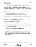
Section
7
VSD
Will
Not
Operate
If
the
VSD
will
not
operate
the
blower
(blower
will
not
spin)
when
the
LMV52
standardization
is
activated,
check
the
following:
1.
Ensure
that
the
VSD
is
activated
through
the
following
menu
path
in
the
LMV52:
Params
&
Display
>
RatioControl
>
Gas/Oil
Settings
>
VSD
=
activated
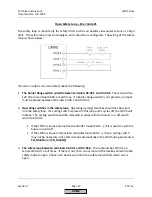
2.
The
VSD
cannot
standardize
if
the
safety
loop
is
open.
Check
that
the
safety
loop
is
closed
by
making
sure
there
is
120
VAC
on
terminal
X3
‐
03.1.
If
there
is
not,
check
the
limits
in
the
safety
loop
and
the
burner
flange
to
see
which
limit
is
open.
3.
Ensure
that
the
LMV52
is
not
in
alarm.
If
so,
reset
the
fault
and
attempt
to
standardize
again.
4.
Verify
that
the
0/4
‐
20
mA
signal
and
the
run/stop
contact
wired
between
the
VSD
and
the
LMV52
are
wired
correctly.
See
Section
2
for
more
information
on
wiring.
5.
Verify
that
the
three
‐
phase
motor
wiring
between
the
VSD
and
the
motor
is
correct.
6.
Verify
that
the
VSD
is
set
up
properly
for
the
motor
it
is
driving.
Specifically,
check
the
following:
The
VSD
should
be
spanned
so
that
0/4mA
equals
0Hz
and
20mA
=
62Hz
(on
a
60
Hz
grid
frequency).
See
Section
5
for
more
information.
The
VSD
is
in
remote
mode
so
that
it
looks
for
a
0/4
‐
20mA
signal
and
a
run/stop
contact.
Closing
the
run/stop
contact
should
cause
the
VSD
to
operate
the
motor.
7.
Disconnect
the
analog
signal
and
run/stop
contact
wires
between
the
VSD
and
the
LMV52.
Use
a
handheld
0/4
‐
20mA
source
and
a
toggle
switch
to
verify
that
the
VSD
responds
to
a
contact
closure
and
a
varying
0/4
‐
20mA
signal.
If
the
VSD
does
not
respond,
correct
the
configuration
of
the
VSD.
If
the
VSD
responds
to
the
contact
closure
and
the
varying
0/4
‐
20mA
signal,
then
go
to
the
next
step.
8.
With
the
wires
between
the
LMV52
and
VSD
still
disconnected,
use
a
multi
‐
meter
to
verify
that
the
LMV52
outputs
about
19.5mA
during
the
standardization
(see
note
below).
Also
verify
that
the
run/stop
contact
in
the
LMV52
closes
and
remains
closed
during
the
standardization.
HOME
Summary of Contents for LMV 5 Series
Page 2: ...Intentionally Left Blank ...
Page 41: ...LMV Series Technical Instructions Document No LV5 1000 SCC Inc Page 7 Section 2 HOME ...
Page 42: ...Technical Instructions LMV Series Document No LV5 1000 Section 2 Page 8 SCC Inc HOME ...
Page 43: ...LMV Series Technical Instructions Document No LV5 1000 SCC Inc Page 9 Section 2 HOME ...
Page 44: ...Technical Instructions LMV Series Document No LV5 1000 Section 2 Page 10 SCC Inc HOME ...
Page 45: ...LMV Series Technical Instructions Document No LV5 1000 SCC Inc Page 11 Section 2 HOME ...
Page 46: ...Technical Instructions LMV Series Document No LV5 1000 Section 2 Page 12 SCC Inc HOME ...
Page 47: ...LMV Series Technical Instructions Document No LV5 1000 SCC Inc Page 13 Section 2 HOME ...
Page 48: ...Technical Instructions LMV Series Document No LV5 1000 Section 2 Page 14 SCC Inc HOME ...
Page 49: ...LMV Series Technical Instructions Document No LV5 1000 SCC Inc Page 15 Section 2 HOME ...
Page 50: ...Technical Instructions LMV Series Document No LV5 1000 Section 2 Page 16 SCC Inc HOME ...
Page 51: ...LMV Series Technical Instructions Document No LV5 1000 SCC Inc Page 17 Section 2 HOME ...
Page 52: ...Technical Instructions LMV Series Document No LV5 1000 Section 2 Page 18 SCC Inc HOME ...
Page 53: ...LMV Series Technical Instructions Document No LV5 1000 SCC Inc Page 19 Section 2 HOME ...
Page 54: ...Technical Instructions LMV Series Document No LV5 1000 Section 2 Page 20 SCC Inc HOME ...
Page 55: ...LMV Series Technical Instructions Document No LV5 1000 SCC Inc Page 21 Section 2 HOME ...
Page 373: ...Intentionally Left Blank ...