

LMV
Series
Technical
Instructions
Document
No.
LV5
‐
1000
SCC
Inc.
Page
15
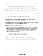
Section
7
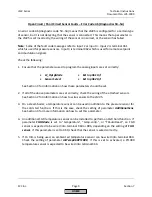
Ambient
or
Stack
Temperature
Sensor
Reading
Incorrectly
If
the
ambient
or
stack
temperature
sensor
wired
into
the
PLL52
are
not
reading
(displayed
as
“XXXX”
on
the
AZL
screen),
or
the
sensors
are
reading
incorrectly,
check
the
following:
1.
Ensure
that
the
sensors
are
wired
into
the
PLL52
module
correctly.
See
Section
2
to
verify
proper
wiring.
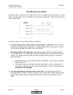
2.
Both
sensors
must
be
a
2
‐
wire,
1000
Ohm,
platinum
or
nickel
RTD.
Check
to
see
that
the
sensors
are
activated
and
properly
configured
under
the
following
menu
paths:
Params
&
Display
>
O2
Module
>
Configuration
>
SupAirTempSens
Params
&
Display
>
O2
Module
>
Configuration
>
FlueGasTempSens
Note:
The
ambient
and
stack
temperature
sensors
are
not
necessary
for
O
2
trim.
However,
if
one
or
both
inputs
are
configured
for
a
sensor
and
either
sensor
is
not
reading,
the
O
2
trim
will
not
activate.
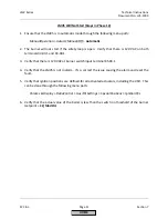
AZL
Says
“
O2
Module
not
active
or
not
Available
”
If
the
AZL
displays
the
message
“O2
Module
not
active
or
not
Available”
when
trying
to
access
one
of
the
following
menus,
the
LMV52
has
lost
communication
with
the
PLL52
O
2
module.
Params
&
Display
>
O2Contr/Alarm
‐
or
‐
Params
&
Display
>
O2
Module
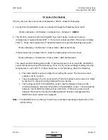
Check
the
CANbus
wiring
between
the
LMV52
and
the
PLL52.
See
Section
2
for
wiring
assistance.
Once
communications
have
been
re
‐
established,
access
to
the
O
2
menus
will
be
allowed.
To
deactivate
the
O
2
module
entirely,
use
the
following
menu
path:
Params
&
Display
>
SystemConfig
>
O2Ctrl/LimitrGas(Oil)
=
man
deact
HOME
Summary of Contents for LMV 5 Series
Page 2: ...Intentionally Left Blank ...
Page 41: ...LMV Series Technical Instructions Document No LV5 1000 SCC Inc Page 7 Section 2 HOME ...
Page 42: ...Technical Instructions LMV Series Document No LV5 1000 Section 2 Page 8 SCC Inc HOME ...
Page 43: ...LMV Series Technical Instructions Document No LV5 1000 SCC Inc Page 9 Section 2 HOME ...
Page 44: ...Technical Instructions LMV Series Document No LV5 1000 Section 2 Page 10 SCC Inc HOME ...
Page 45: ...LMV Series Technical Instructions Document No LV5 1000 SCC Inc Page 11 Section 2 HOME ...
Page 46: ...Technical Instructions LMV Series Document No LV5 1000 Section 2 Page 12 SCC Inc HOME ...
Page 47: ...LMV Series Technical Instructions Document No LV5 1000 SCC Inc Page 13 Section 2 HOME ...
Page 48: ...Technical Instructions LMV Series Document No LV5 1000 Section 2 Page 14 SCC Inc HOME ...
Page 49: ...LMV Series Technical Instructions Document No LV5 1000 SCC Inc Page 15 Section 2 HOME ...
Page 50: ...Technical Instructions LMV Series Document No LV5 1000 Section 2 Page 16 SCC Inc HOME ...
Page 51: ...LMV Series Technical Instructions Document No LV5 1000 SCC Inc Page 17 Section 2 HOME ...
Page 52: ...Technical Instructions LMV Series Document No LV5 1000 Section 2 Page 18 SCC Inc HOME ...
Page 53: ...LMV Series Technical Instructions Document No LV5 1000 SCC Inc Page 19 Section 2 HOME ...
Page 54: ...Technical Instructions LMV Series Document No LV5 1000 Section 2 Page 20 SCC Inc HOME ...
Page 55: ...LMV Series Technical Instructions Document No LV5 1000 SCC Inc Page 21 Section 2 HOME ...
Page 373: ...Intentionally Left Blank ...