

Technical
Instructions
LMV
Series
Document
No.
LV5
‐
1000
Section
6
Page
26
SCC
Inc.
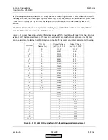
If
only
the
O
2
alarm
function
is
to
be
used
and
the
O
2
trim
has
not
been
commissioned,
a
few
key
parameters
must
be
set.
These
are:
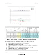
1.
O2
MaxValue
‐
set
to
the
maximum
safe
%O
2
(wet)
for
all
points.
2.
O2
Alarm
curve
‐
enter
the
minimum
safe
%O
2
(wet)
for
each
point.
3.
Tau
Low
‐
FireOEM
‐
the
delay
time
of
the
burner
/
boiler
at
low
fire
4.
Tau
High
‐
FireOEM
‐
the
delay
time
of
the
burner
/
boiler
at
high
fire
5.
OptgMode
‐
set
to
O2
Limiter
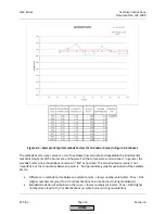
If
the
O
2
trim
has
not
been
commissioned,
it
will
be
necessary
to
manually
enter
Tau
Low
‐
FireOEM
and
Tau
High
‐
FireOEM
.
These
Tau
times
do
not
have
to
be
as
accurate
as
if
the
O
2
trim
was
being
used.
These
can
be
manually
timed
by
using
the
O
2
reading
on
the
AZL
(recommended),
or
typical
values
can
be
used.
Higher
turndown
burners
will
produce
longer
low
fire
Tau
times.
Typically,
for
a
5
‐
to
‐
1
turndown
burner,
Tau
Low
‐
FireOEM
is
between
10
‐
20
seconds.
Tau
High
‐
FireOEM
is
typically
4
seconds
or
less.
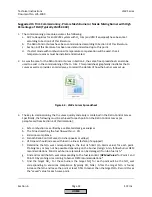
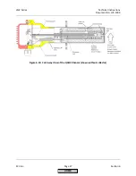
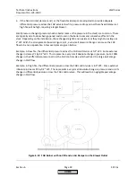
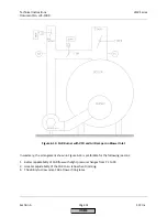
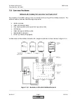
How
the
O
2
is
Measured
with
the
QGO20
Sensor
and
PLL52
Module
The
QGO20
is
a
Zirconium
type
sensor
that
is
heated
to
approximately
1292°F.
The
high
temperatures
allow
oxygen
to
diffuse
through
the
Zirconium
cell
and
produce
a
milli
‐
volt
signal.
This
milli
‐
volt
signal
is
referred
to
as
the
Nernst
Voltage.
The
Nernst
Voltage
that
is
produced
for
a
given
%O
2
is
dependent
on
the
concentration
of
oxygen
and
the
temperature
of
the
Zirconium
cell.
The
PLL52
module
reads
both
the
Nernst
Voltage
and
the
temperature
of
the
Zirconium
cell.
With
this
information,
the
%O
2
can
be
accurately
determined
and
sent
back
to
the
LMV52
over
CANbus.
As
well
as
taking
the
milli
‐
volt
signals
and
converting
these
to
CANbus
data,
the
PLL52
also
serves
as
the
controller
for
the
Zirconium
cell's
heating
element.
The
PLL52
is
also
a
place
to
connect
the
combustion
air
temperature
sensor
and
the
stack
gas
temperature
sensor.
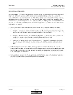
Three
milli
‐
volt
signals
originate
in
the
QGO20:
1.
Nernst
Voltage
from
the
Zirconium
oxide
O
2
cell
terminals
B1
and
M
2.
O
2
cell
thermocouple
signal
terminals
B2
and
M
3.
Cold
junction
thermocouple
compensation
terminals
G2
and
U3
These
three
milli
‐
volt
signals
between
the
QGO20
and
the
PLL52
must
be
run
in
a
separate
conduit
and
/
or
a
shielded
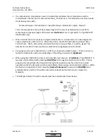
cable.
See
Section
2
for
complete
details
on
wiring
the
QGO20
to
the
PLL52.
High
voltage
wires
are
also
connected
from
the
PLL52
to
the
QGO20
for
the
heater.
It
is
very
important
that
these
wires
are
run
in
a
separate
conduit
away
from
the
milli
‐
volt
signals.
NOTE:
Never
connect
the
QGO20
heater
directly
to
line
voltage!
Permanent
damage
will
result
to
the
heating
element
and
the
sensor.
High
voltage
wires
for
the
heater
to
the
QGO20
must
come
from
the
PLL52
module.
See
Section
2
for
more
information.
Also,
due
to
possible
interference
on
the
milli
‐
volt
signals,
the
PLL52
must
be
installed
within
30
feet
of
the
QGO20.
HOME
Summary of Contents for LMV 5 Series
Page 2: ...Intentionally Left Blank ...
Page 41: ...LMV Series Technical Instructions Document No LV5 1000 SCC Inc Page 7 Section 2 HOME ...
Page 42: ...Technical Instructions LMV Series Document No LV5 1000 Section 2 Page 8 SCC Inc HOME ...
Page 43: ...LMV Series Technical Instructions Document No LV5 1000 SCC Inc Page 9 Section 2 HOME ...
Page 44: ...Technical Instructions LMV Series Document No LV5 1000 Section 2 Page 10 SCC Inc HOME ...
Page 45: ...LMV Series Technical Instructions Document No LV5 1000 SCC Inc Page 11 Section 2 HOME ...
Page 46: ...Technical Instructions LMV Series Document No LV5 1000 Section 2 Page 12 SCC Inc HOME ...
Page 47: ...LMV Series Technical Instructions Document No LV5 1000 SCC Inc Page 13 Section 2 HOME ...
Page 48: ...Technical Instructions LMV Series Document No LV5 1000 Section 2 Page 14 SCC Inc HOME ...
Page 49: ...LMV Series Technical Instructions Document No LV5 1000 SCC Inc Page 15 Section 2 HOME ...
Page 50: ...Technical Instructions LMV Series Document No LV5 1000 Section 2 Page 16 SCC Inc HOME ...
Page 51: ...LMV Series Technical Instructions Document No LV5 1000 SCC Inc Page 17 Section 2 HOME ...
Page 52: ...Technical Instructions LMV Series Document No LV5 1000 Section 2 Page 18 SCC Inc HOME ...
Page 53: ...LMV Series Technical Instructions Document No LV5 1000 SCC Inc Page 19 Section 2 HOME ...
Page 54: ...Technical Instructions LMV Series Document No LV5 1000 Section 2 Page 20 SCC Inc HOME ...
Page 55: ...LMV Series Technical Instructions Document No LV5 1000 SCC Inc Page 21 Section 2 HOME ...
Page 373: ...Intentionally Left Blank ...