


LMV
Series
Technical
Instructions
Document
No.
LV5
‐
1000
SCC
Inc.
Page
5
Section
4
6.
LMV52
/
VFD
combination
must
be
“Standardized”
before
operation.
See
Section
5
(VSD)
for
more
details.
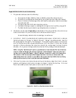
a.
Verify
that
the
air
damper
opens
to
pre
‐
purge
position
before
the
blower
is
energized
for
standardization.
Pre
‐
Requisites
for
LMV52
Systems
with
O2
Trim
1.
All
prerequisites
of
the
Basic
LMV51
system
apply.
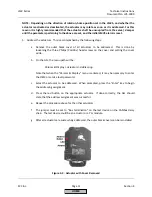
2.
The
O
2
sensor
must
be
mounted
correctly.
See
Appendix
B
(LMV5
Accessories
Guide)
for
more
details.
Particular
attention
should
be
paid
to
the
following:
a.
If
the
O
2
sensor
cannot
be
installed
per
Appendix
B
(LMV5
Accessories
Guide),
contact
SCC
for
assistance.
b.
The
QGO20
O
2
sensor
is
not
suited
for
most
types
of
biogas
or
fuels
that
produce
ash,
such
as
#6
oil.
Contact
SCC
for
advice
on
the
compatibility
of
uncommon
fuels.
3.
The
O
2
sensor
must
be
wired
to
the
PLL52
correctly.
See
Section
2
(Wiring)
for
more
details.
Particular
attention
should
be
paid
to
the
following:
a.
The
PLL52
module
must
be
within
30
feet
of
the
O
2
sensor.
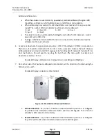
b.
Two
conduits
must
be
run
between
the
QGO20
O
2
sensor
and
the
PLL52
module.
One
conduit
must
contain
the
low
voltage
signals
while
the
other
conduit
must
contain
the
high
voltage
for
the
sensor
heater.
4.
The
furnace
pressure
of
the
boiler
being
commissioned
must
be
repeatable
at
a
given
firing
rate.
Repeatability
of
+/
‐
0.2
in
WC
at
each
firing
rate
is
adequate.
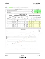
5.
A
fuel
flow
meter
or
some
means
of
determining
the
load
(firing
rate)
to
+/
‐
3%
is
required.
A
more
accurate
load
number
(+/
‐
3%)
for
each
curve
point
is
necessary
for
reliable
O
2
trim
functionality.
6.
The
LMV52
must
be
powered
and
configured
for
the
QGO20
O
2
sensor
for
two
hours
prior
to
commissioning.
This
is
done
to
let
the
QGO20
sensor
heat
up
thoroughly.
7.
The
boiler
must
be
up
to
normal
operating
temperature
/
pressure
for
at
least
one
hour
before
commissioning
the
O
2
trim.
HOME
Summary of Contents for LMV 5 Series
Page 2: ...Intentionally Left Blank ...
Page 41: ...LMV Series Technical Instructions Document No LV5 1000 SCC Inc Page 7 Section 2 HOME ...
Page 42: ...Technical Instructions LMV Series Document No LV5 1000 Section 2 Page 8 SCC Inc HOME ...
Page 43: ...LMV Series Technical Instructions Document No LV5 1000 SCC Inc Page 9 Section 2 HOME ...
Page 44: ...Technical Instructions LMV Series Document No LV5 1000 Section 2 Page 10 SCC Inc HOME ...
Page 45: ...LMV Series Technical Instructions Document No LV5 1000 SCC Inc Page 11 Section 2 HOME ...
Page 46: ...Technical Instructions LMV Series Document No LV5 1000 Section 2 Page 12 SCC Inc HOME ...
Page 47: ...LMV Series Technical Instructions Document No LV5 1000 SCC Inc Page 13 Section 2 HOME ...
Page 48: ...Technical Instructions LMV Series Document No LV5 1000 Section 2 Page 14 SCC Inc HOME ...
Page 49: ...LMV Series Technical Instructions Document No LV5 1000 SCC Inc Page 15 Section 2 HOME ...
Page 50: ...Technical Instructions LMV Series Document No LV5 1000 Section 2 Page 16 SCC Inc HOME ...
Page 51: ...LMV Series Technical Instructions Document No LV5 1000 SCC Inc Page 17 Section 2 HOME ...
Page 52: ...Technical Instructions LMV Series Document No LV5 1000 Section 2 Page 18 SCC Inc HOME ...
Page 53: ...LMV Series Technical Instructions Document No LV5 1000 SCC Inc Page 19 Section 2 HOME ...
Page 54: ...Technical Instructions LMV Series Document No LV5 1000 Section 2 Page 20 SCC Inc HOME ...
Page 55: ...LMV Series Technical Instructions Document No LV5 1000 SCC Inc Page 21 Section 2 HOME ...
Page 373: ...Intentionally Left Blank ...