INSTALLATION GUIDE
IGWiPS200-1
Rev 3
May 2007
)
)
)
)
)
)
)
)
)
)
)
(
(
(
(
(
(
(
(
(
(
(
(
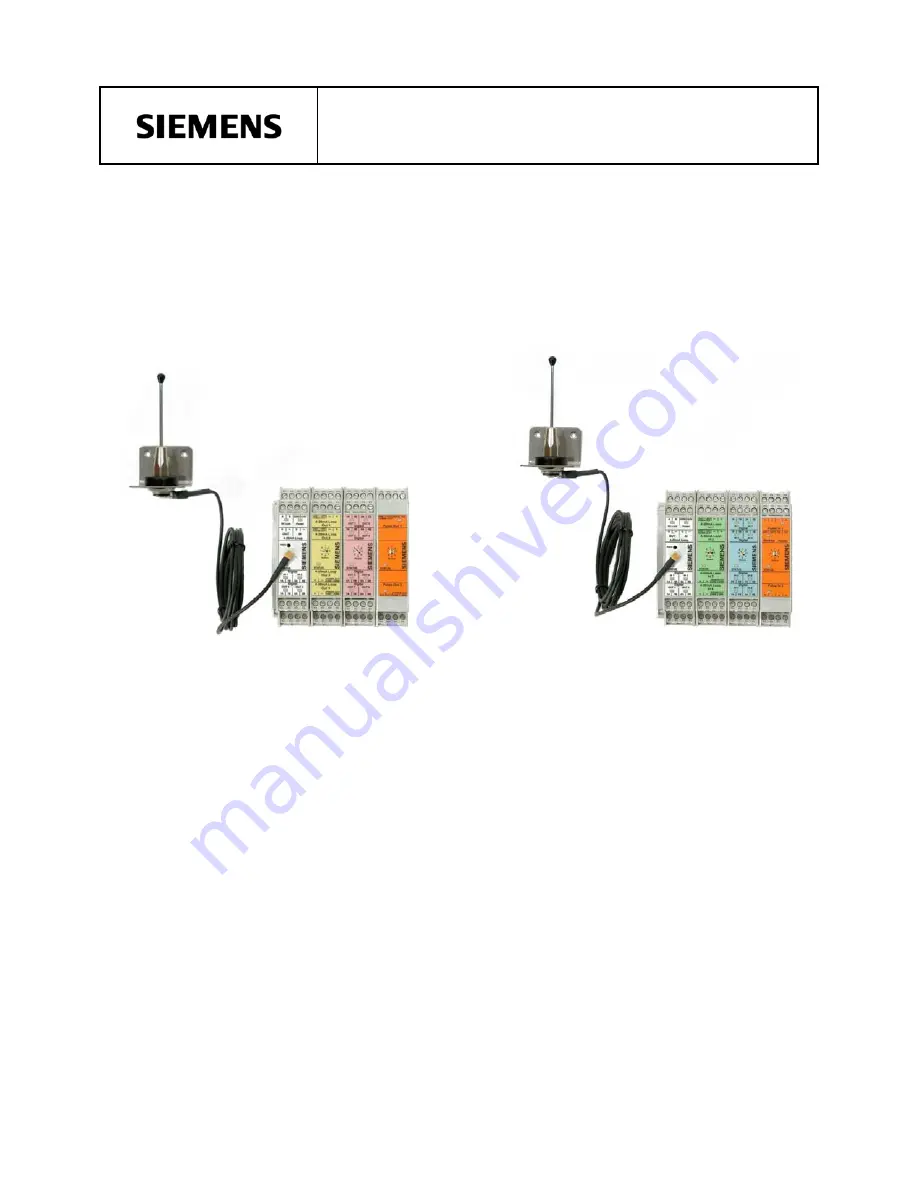
WiPS-200 Series
Wireless Process Solution
Frequency Hopping Spread Spectrum Radio
Two-Way (Multipoint-to-Point) for Monitoring and Control
With Expandable I/O Options


