


Building Technologies
Fire safety and security products
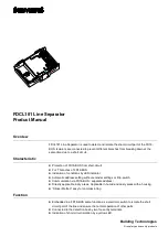
FDCL181 Line Separator
Product Manual
Overview
FDCL181 Line Separator is used to detect and isolate the short-circuit part of the FD18-
BUS. Isolators are connected to prevent different branches from breaking down at the
same time due to a short circuit.
Characteristic
l
Protection of FD18-BUS from short-circuit
l
For T branches of FD18-BUS
l
Indication of conditions by LED indicator
l
Automatic address setting without encoder settings or Dip-switch
l
Communication via FD18-BUS
(
separate address
)
l
Directly applicable in dry areas. Applicable in humid and dusty areas with a housing
l
“
Sticker Method
”
easy for commissioning
Function
l
Embedded in a FD18-BUS same function as a electronic switch to isolate the short
circuit part of the line and ensure the normal operation of other parts.
l
Connected to the detection bus by two four-entry terminals.
l
Indication of short circuit isolation by a yellow LED.