03/03
Configuration
CP 243-1 IT
J31069-D0429-U001-A0-7618
69
4.4.1
Assigned System Marker Area (SM Area)
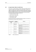
The CP 243-1 IT occupies 50 bytes in the system marker area of the S7-200 CPU.
The address of these 50 bytes depends on the current position a CP 243-1 IT oc-
cupies in an S7-200 system. These 50 bytes primarily contain general information
and status information of the CP 243-1 IT. The last four bytes contain a pointer with
which the configuration data of the CP 243-1 IT can be accessed. These configura-
tion data are located consecutively in the variable memory of the S7-200 CPU.
These data are divided into the following data blocks.
•
Configuration Data Block (CDB)
•
Network Parameter Block (NPB)
•
Network Data Block (NDB)
•
Internet Data Block (IDB)
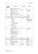
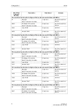
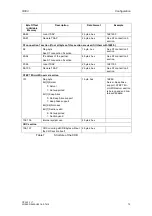
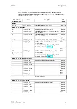
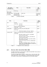
The following table shows the relationship between the position of a module in the
S7-200 system and the related system marker area.
Position in S7-200
System
Occupied
Marker Area
Remarks
CPU -
-
0
200 to 249
-
1
250 to 299
Only supported for CPU firmware versions
starting with 1.2
2
300 to 349
Only supported for CPU firmware versions
starting with 1.2
3
350 to 399
Only supported for CPU firmware versions
starting with 1.2
4
400 to 449
Only supported for CPU firmware versions
starting with 1.2
5
450 to 499
Only supported for CPU firmware versions
starting with 1.2
6
500 to 549
Only supported for CPU firmware versions
starting with 1.2
Table 6
System marker area
Summary of Contents for CP 243-1 IT
Page 46: ...Installation and Commissioning 03 03 CP 243 1 IT J31069 D0429 U001 A0 7618 46 ...
Page 94: ...Programming 03 03 CP 243 1 IT J31069 D0429 U001 A0 7618 94 ...
Page 106: ...Diagnosis 03 03 CP 243 1 IT J31069 D0429 U001 A0 7618 106 ...
Page 120: ...Technical Data 03 03 CP 243 1 IT J31069 D0429 U001 A0 7618 120 ...
Page 130: ...Example 03 03 CP 243 1 IT J31069 D0429 U001 A0 7618 130 ...

