03/03
Installation and Commissioning
CP 243-1 IT
J31069-D0429-U001-A0-7618
47
3 Installation
and
Commissioning
Installation
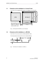
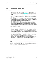
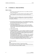
You can install the devices of the S7-200 family either in an operator panel or on a
DIN rail. You can arrange the modules both horizontally and vertically. The S7-200
CPU and the expansion modules are designed for natural heat dissipation via con-
vection. For this reason, leave at least 25 mm of free space above and below the
devices so that the heat is free to escape. Long operating times at maximum ambi-
ent temperatures and maximum loads will shorten the lifespan of the electronic
components of the device.
Note
The position in an S7-200 system in which a CP 243-1 IT can be operated de-
pends on the firmware version of the S7-200 CPU you are using.
With a firmware version greater than or equal to 1.2, the CP 243-1 IT can be used
in any position in an S7-200 system. With a firmware version less than 1.2, the CP
243-1 IT must be installed directly next to the S7-200 CPU.
Wiring
!
Warning
If you attempt to install or remove the CP 243-1 IT or other devices while they
are on, you may receive an electric shock or the devices may not work properly.
If the power is not switched off for the CP 243-1 IT and all connected devices
while the devices are being installed/removed, this may cause injury and/or
property damage.
Take all necessary safety precautions and make sure that the power for the S7-
200 and the CP 243-1 IT is turned off before you begin wiring.
Summary of Contents for CP 243-1 IT
Page 46: ...Installation and Commissioning 03 03 CP 243 1 IT J31069 D0429 U001 A0 7618 46 ...
Page 94: ...Programming 03 03 CP 243 1 IT J31069 D0429 U001 A0 7618 94 ...
Page 106: ...Diagnosis 03 03 CP 243 1 IT J31069 D0429 U001 A0 7618 106 ...
Page 120: ...Technical Data 03 03 CP 243 1 IT J31069 D0429 U001 A0 7618 120 ...
Page 130: ...Example 03 03 CP 243 1 IT J31069 D0429 U001 A0 7618 130 ...


