Semiconductor Group
6-87
1999-04-01
On-Chip Peripheral Components
C541U
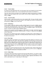
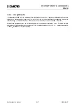
6.4.11 Detach / Attach Detection
The USB device can be used in two different modes concerning its power supply, the bus-powered
mode and the self-powered mode.
6.4.11.1 Self-Powered Mode
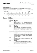
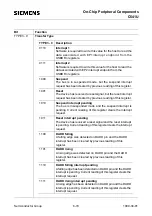
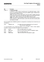
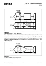
In self-powered mode, the USB device has its own power supply. The USB device has to detect
whether it is connected to USB bus or not. This detection is done by hardware by using the Device-
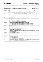
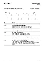
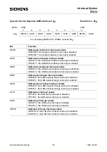
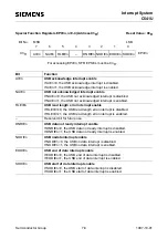
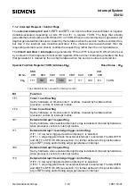
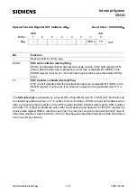
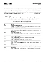
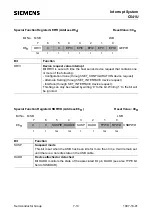
Attached Device-Detached pin DADD. When the device-attached condition is detected, bit DA in
the device control register DCR is set and a device interrupt can be generated if required (bit DAI in
SFR DIRR is set). The interrupt service routine of this device interrupt must completely initialize the
USB device/module. The device-detached detection resets bit DA (and sets bit DDI in SFR DIRR)
and can generate a device interrupt, too.
6.4.11.2 Bus-Powered Mode
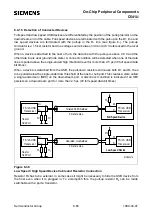
In bus-powered mode, the USB device is driven by the power supply from the USB bus. The
maximum power consumption is given by the USB specification. In order to respect this
specification, the power consumption in suspend mode should not exceed 500
µ
A.
An explicit device-attached detection in this mode is not necessary. If the CPU is running, the device
is attached, so the USB device/module has to be configured only after power-on. The device-detach
action has no significance concerning software, because the device is no longer powered and the
CPU stops. As a result, no attach-detach detection is needed. In this mode, pin DADD can be used
as standard IO pin with bit DA monitoring its status and the interrupt generation on DA should not
be used. If the interrupt generation on bit DA remains activated, a request must not be interpreted
as attached-detached action, but as an external interrupt request on pin DADD, which is generating
a device interrupt.
Summary of Contents for C541U
Page 1: ... 8 LW 026 0LFURFRQWUROOHU 8VHU V 0DQXDO http www siem ens d Sem iconductor ...
Page 7: ......
Page 21: ...Semiconductor Group 2 6 1997 10 01 Fundamental Structure C541U ...
Page 37: ...Semiconductor Group 4 6 1997 10 01 External Bus Interface C541U ...
Page 133: ...Semiconductor Group 6 88 1999 04 01 On Chip Peripheral Components C541U ...
Page 163: ...Semiconductor Group 8 8 1997 10 01 Fail Safe Mechanisms C541U ...
Page 185: ...Semiconductor Group 10 14 1997 10 01 OTP Memory Operation C541U ...

