
7SR210 & 7SR220 Commissioning & Maintenance Guide
© 2013 Siemens Protection Devices Limited
Page 25 of 82
2.1
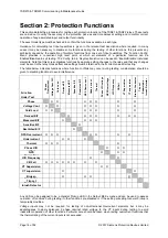
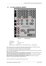
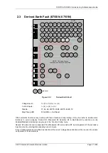
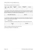
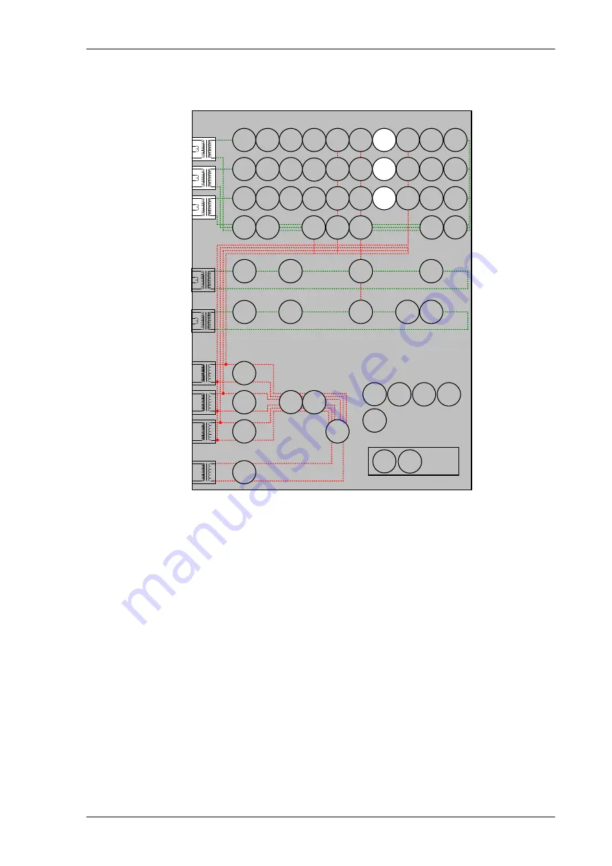
Arc Flash Detection (50AFD)
46
BC
46
NPS
(x2)
37
(x2)
49
50
BF
V
L1
(V
A
)
V
L2
(V
B
)
V
L3
(V
C
)
V
4
(V
X
)
I
L1
(I
A
)
81
HBL
2/5
37
(x2)
49
50
BF
I
L2
(I
B
)
81
HBL
2/5
37
(x2)
49
50
BF
I
L3
(I
C
)
81
HBL
2/5
60
CTS
I
4
(I
G
)
I
5
(I
SEF
)
74
TCS
NOTE: The use of some
functions are mutually exclusive
67/
50/51
(x4)
67/
50/51N
(x4)
67/
50/51
(x4)
67/
50/51
(x4)
67/
50/51G
(x4)
67/
50/51S
(x4)
64
H
27
59
27
59
(x4)
27
59
(x4)
27
59
(x4)
47
(x2)
81
(x6)
79
Optional
59N
(x2)
81
HBL
2/5N
37G
(x2)
37S
(x2)
51c
60
CTS-
I
60
CTS-
I
60
CTS-
I
37
50
BF
37
50
BF
25
50
AFD
50
AFD
50
AFD
51c
51c
51c
32S
32
55
21
LB
21
LB
21
LB
51V
21FL
60
VTS
51V
51V
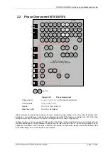
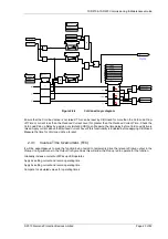
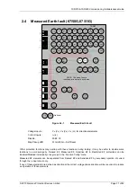
Figure 2.1-1
Arc Flash Detection
Voltage Inputs:
N/A
Current Inputs:
I
L1
(I
A
), I
L2
(I
B
), I
L3
(I
C
),
Disable:
49, 50, 51
Map Pickup LED: 50AFD Zone-n Flash - Hand Reset, 50AFD Zone-n – Hand/self Reset
The overcurrent level can be tested without an arc flash by separately energising or inverting the arc detector
binary input continuously for the duration of the test for the zone being tested.
If the current setting is low, gradually increase current until element operates.
If the current level required is greater than the thermal limit of the relay, apply 0.9x setting, check for no operation,
apply 1.1x setting, check operation.
Optical sensors such as 7XG31 can be tested by application of a suitable light source. Relay instrumentation can
be used to indicate binary input pickup or by the 50AFD Zone-n Flash outputs.
The 7XG31 devices will typically require 10000 lx light level for 1.25ms to trigger. A high powered photographic
flash is the most convenient means of initiating positive sensor operation.
Note that mobile phone or small compact camera flashes may not have sufficient power to cause sensor
operation but may be suitable if held directly against the sensor.
Check correct indication, trip output, alarm contacts, waveform record.
Summary of Contents for Argus 7SR21
Page 1: ...Energy Management 7SR21 7SR22 Argus Overcurrent Relay Reyrolle Protection Devices ...
Page 2: ......
Page 4: ...Contents 7SR11 and 7SR12 Page 2 of 2 2018 Siemens Protection Devices Limited ...
Page 185: ...7SR210 Settings Guide Unrestricted 2018 Siemens Protection Devices Limited Page 61 of 61 ...
Page 277: ...7SR220 Settings Guide Unrestricted Page 72 of 107 2013 Siemens Protection Devices Limited ...
Page 382: ...7SR220 Technical Manual Chapter 4 Page 2 of 96 2017 Siemens Protection Devices Limited ...
Page 386: ...7SR220 Technical Manual Chapter 4 Page 6 of 96 2017 Siemens Protection Devices Limited ...
Page 398: ...7SR220 Technical Manual Chapter 4 Page 18 of 96 2017 Siemens Protection Devices Limited ...
Page 414: ...7SR220 Technical Manual Chapter 4 Page 34 of 96 2017 Siemens Protection Devices Limited ...
Page 466: ...7SR220 Technical Manual Chapter 4 Page 86 of 96 2017 Siemens Protection Devices Limited ...
Page 468: ...7SR220 Technical Manual Chapter 4 Page 88 of 96 2017 Siemens Protection Devices Limited ...
Page 470: ...7SR220 Technical Manual Chapter 4 Page 90 of 96 2017 Siemens Protection Devices Limited ...
Page 472: ...7SR220 Technical Manual Chapter 4 Page 92 of 96 2017 Siemens Protection Devices Limited ...
Page 643: ...Unrestricted ...