


7SR11 & 7SR12 Commissioning and Maintenance Guide
©2017 Siemens Protection Devices Limited
Chapter 6 Page 49 of 72
Where two NPS elements are being used with different settings, it is convenient to test the elements with the
highest settings first. The elements with lower settings can then be tested without disabling the lower settings.
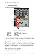
NPS Overvoltage can be tested using a normal 3P balanced source. Two phase voltage connections should be
reversed so that the applied balanced 3P voltage is Negative Phase Sequence.
If the 47-n delay is small, gradually increased the applied balanced 3P voltage until element operates.
If DTL is large apply 0.9x setting, check for no operation, apply 1.1x setting, check operation
Apply 2x setting current if possible and record operating time
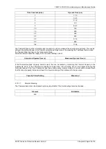
Setting
(Volts)
Delay
(sec)
Hyst.
P.U.
(Volts)
D.O
(Volts)
Op. Time
@ 2x Vs
U/V Guard
Tolerance
NPS
2.14.3.1
Element Blocking
The NPS Overvoltage element can be blocked by Binary Input Inhibit. This functionality should be checked.
Element
BI Inhibits
47-1
47-2
Check correct indication, trip output, alarm contacts, waveform record.
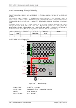
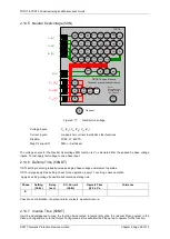
2.14.4 Undervoltage Guard (47 U/V Guard)
If any 47 NPS overvoltage element is set to be inhibited by the 47 Undervoltage Guard element, this function
should be tested.
Connect the test voltage inputs to suit the installation wiring diagram utilising any test socket facilities available. It
may be useful to temporarily map an LED as ‘General Pickup’ to assist during testing. 47UVG operation will reset
the General Pickup if no other element is operated. This LED should not be set as ‘Hand Reset’ in the Output
matrix.
Starting from nominal voltage, apply a step decrease to the applied voltage to a level below the 47 NPS voltage
setting but above the 47UVG setting such that an NPS Overvoltage element operation occurs. Slowly reduce the
applied voltage until the 47 NPS voltage element resets, this can be detected by the General Pickup LED reset if
no other element is operated (this includes any Undervoltage element which is not UV Guarded).
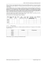
Phase
Setting
(Volts)
Tolerance
V element
Used for test
Blocked
Volts
NOTES
UVG
Summary of Contents for Argus 7SR11
Page 1: ...Energy Management 7SR11 7SR12 Argus Overcurrent Relay Reyrolle Protection Devices ...
Page 2: ......
Page 4: ...7SR11 7SR12 Argus Contents 2015 Siemens Protection Devices Limited Page 2 of 2 ...
Page 170: ...7SR120 Technical Manual Chapter 4 Page 2 of 84 2017 Siemens Protection Devices Limited ...
Page 174: ...7SR120 Technical Manual Chapter 4 Page 6 of 84 2017 Siemens Protection Devices Limited ...
Page 196: ...7SR120 Technical Manual Chapter 4 Page 28 of 84 2017 Siemens Protection Devices Limited ...
Page 242: ...7SR120 Technical Manual Chapter 4 Page 74 of 84 2017 Siemens Protection Devices Limited ...
Page 244: ...7SR120 Technical Manual Chapter 4 Page 76 of 84 2017 Siemens Protection Devices Limited ...
Page 246: ...7SR120 Technical Manual Chapter 4 Page 78 of 84 2017 Siemens Protection Devices Limited ...
Page 254: ...7SR11 7SR12 Installation Guide Chapter 5 Page 2 of 32 2017 Siemens Protection Devices Limited ...
Page 358: ...7SR11 7SR12 Applications Guide Page 2 of 48 2017 Siemens Protection Devices Limited ...
Page 405: ......


