INSTALLATION AND CONFIGURATION
2-33
Document No.: COM-00-05-16 June 2006, Revised June 2014
Version: C.1
b.
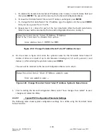
To change the digit of the second field of the WAG Circuit ID, type the digit and then
press
ENTER
. Entry can be any value from 1 to 3. Go to step 4.
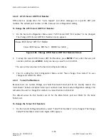
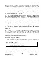
Figure 2-43. Change WAG Routing Region Screen – After Digits Entered In First Field
4.
From the screen in figure 2-44, do one of the following:
a.
To leave the digits of the third field of a currently assigned WAG Circuit ID unchanged,
press
ENTER
.
b.
To change the digits of the third field of the WAG Circuit ID, type the digits and then press
ENTER
. Entry can be any value from 1 to 15.
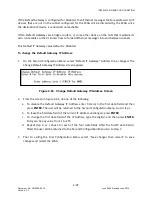
The user will be returned to the Second Configuration Menu. The WAG Circuit ID is displayed.
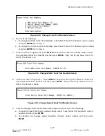
Figure 2-44. Change WAG Routing Region Screen – After Digits Entered In Second Field
5.
Prior to exiting the First Configuration Menu, “Save changes then restart” to save changes and
restart the WAG.
2.6.18
Routing Region Domain 1
Routing Region Domain 1 consists of four data fields and is intended to contain an IP address (if
the first field is set to 0, the function is disabled). The IP address can be a single IP address
(unicast) or it can be a multicast or broadcast address such as 255.255.255.255.
This address is typically the IP address of a Packet Switch that handles the necessary LLL routing
regions, or a computer running the Office Communications Gateway (OCG) software that will
handle the routing regions. This address can also be the IP address of AServer.
If a broadcast IP address is configured here (all 255s) then “route request” messages sent by the
WAG to resolve the route for an LLL will be broadcast on the Ethernet LAN.


