background image

INSTALLATION AND CONFIGURATION 

2-3 

Document No.: COM-00-05-16                                                                                                       June 2006, Revised June 2014 
Version: C.1 

2.3.2

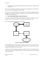
    Connecting to an Ethernet Hub 

The following diagram shows an Ethernet hub connected to the WAG. 


Figure 2-2.  Ethernet Hub


Summary of Contents for A53457

Page 1: ...Y WAG A53457 JUNE 2006 REVISED JUNE 2014 DOCUMENT NO COM 00 05 16 VERSION C 1 Siemens Industry Inc Rail Automation 9568 Archibald Ave Suite 100 Rancho Cucamonga California 91730 1 800 793 7233 Copyright 2014 Siemens Industry Inc Rail Automation All rights reserved ...

Page 2: ...ss of any information contained in any translation of manual or product information from its original official released version in English and shall not be liable for any losses caused by such reliance on the accuracy reliability or timeliness of such information Any person or entity who relies on translated information does so at his or her own risk WARRANTY INFORMATION Siemens Industry Inc Rail ...

Page 3: ... 4 paragraph 1 3 Re titled paragraph PERSISTENT SERIAL TUNNELING Provided diagram and verbiage to fully explain WAG communication through the LAN Changed the wording of all subparagraphs following Figure 1 2 to present a more accurate operational description for the WAG Page 1 5 paragraph 1 4 Re titled paragraph OFFICE SYSTEM INTERFACE OSI Provided diagram and verbiage to fully explain WAG communi...

Page 4: ... adding Figure 2 13 Type 7 ATCS Address Configuration Screen with functional explanations Page 2 13 subparagraph 2 6 2 Type 3 ATCS Address Item 1 replaced Figure 2 14 ATCS Address Screen with one that specifies the second line ATCS address item as Enter the NN Page 2 13 paragraph 2 6 2 Type 3 ATCS Address subparagraph 2 6 2 Changed subparagraph title to read Type 3 ATCS Address and reworded entire...

Page 5: ...subparagraph 2 6 21 Genisys Wait Poll Response with appropriate figures Page 2 37 paragraph 2 6 CONFIGURATION OF THE WAG Added subparagraph 2 6 22 ATCS Retry Wait with appropriate figures Page 2 38 paragraph 2 6 CONFIGURATION OF THE WAG Added subparagraph 2 6 23 ATCS Max Retries with appropriate figures Page 2 38 paragraph 2 6 CONFIGURATION OF THE WAG Added subparagraph 2 6 24 Genisys Poll Startin...

Page 6: ... VIEWING THE STATUS Added two subparagraphs that read The last line of the XPORT and In the event Page 3 3 paragraph 3 2 VIEWING THE STATUS Added subparagraph 3 2 1 1 Additional Status Information When Configured of OSI Page 3 5 paragraph 3 6 Re titled paragraph PERSISTANT SERIAL TUNNEL COMMAND Provided diagram and verbiage to fully explain WAG Persistent Serial Tunnel configuration Renumbered the...

Page 7: ... 2 Send File Pop up Window Replaced image with one more accurate and appropriate for this manual Page 5 2 Figure 5 3 Zmodem File Send Screen Replaced image with one more accurate and appropriate for this manual Page 5 4 Figure 5 4 Zmodem File Receive Screen Replaced image with one more accurate and appropriate for this manual Page 6 2 paragraph 6 3 Reformatted CAUTION statement to remove extra spa...

Page 8: ...nd 1 10 1 2 Page 1 13 Added paragraph headings 1 10 1 3 through 1 10 1 5 Page 1 14 Added paragraph headings 1 10 2 1 11 1 11 1 and 1 11 2 Page 1 15 Added paragraph headings 1 11 3 through 1 11 5 Page 2 6 Added new paragraph 2 3 5 Persistent Serial Tunneling Configuration Added figures 2 5 and 2 6 Page 2 7 Added paragraph 2 3 6 Office System Interface Configuration Added figure 2 7 Page 2 9 Added t...

Page 9: ... Updated paragraph number to 2 6 17 Updated figure reference to 2 42 Page 2 35 Updated figure number to 2 43 and reference in following sentence Updated paragraph heading number to 2 6 18 Acronym spelled out on the first occurrence on the previous page Page 2 36 Updated figure references in two places to 2 45 Page 2 37 Updated figure reference to 2 46 Updated paragraph heading to 2 6 19 ripple for...

Page 10: ... IP Redundancy to Serial and Telnet Page 3 14 Added new paragraph Time Stamp on Trace Page 3 15 and 3 16 To paragraph 3 18 second paragraph added the phrase on how to save displays to a file Added System to run time on list Page 3 28 through 3 30 Added paragraph entitled Event Log Streaming and paragraphs 3 22 through 3 25 Page 5 1 Updated figure 5 1 with new screen shot Page 5 3 Updated figure 5 ...

Page 11: ...LD RESULT IN DEATH OR SERIOUS INJURY WARNINGS ALWAYS TAKE PRECEDENCE OVER NOTES CAUTIONS AND ALL OTHER INFORMATION CAUTION REFERS TO PROPER PROCEDURES OR PRACTICES WHICH IF NOT STRICTLY OBSERVED COULD RESULT IN A POTENTIALLY HAZARDOUS SITUATION AND OR POSSIBLE DAMAGE TO EQUIPMENT CAUTIONS TAKE PRECEDENCE OVER NOTES AND ALL OTHER INFORMATION EXCEPT WARNINGS NOTE Generally used to highlight certain ...

Page 12: ...rovided grasp the edge of the circuit board but avoid touching circuit traces or components Handle circuit boards by the edges only Never physically touch circuit board or connector contact fingers or allow these fingers to come in contact with an insulator e g plastic rubber etc When not in use place circuit boards in approved static shielding bags contact fingers first Remove circuit boards from...

Page 13: ...s for J1 1 5 1 3 1 2 Pinouts for J2 1 5 1 3 1 3 Pinouts for J3A J3B 1 6 1 3 1 4 Pinouts for J4 1 6 1 3 1 5 Echelon Interface J4 Characteristics 1 6 1 3 2 LED Indicators 1 7 1 4 PRODUCT SPECIFICATIONS 1 7 1 4 1 Physical Specifications 1 7 1 4 2 Dimensions 1 7 1 4 3 Power Specifications 1 7 1 4 4 Environmental Specifications 1 7 1 4 5 Default Factory Settings 1 8 1 5 PERSISTENT SERIAL TUNNELING PST ...

Page 14: ... Echelon Address 2 17 2 6 7 UDP Port Assignments 2 18 2 6 8 Router Expiration Timer 2 19 2 6 9 Broadcast Medium 2 19 2 6 10 TCP Port Assignments 2 20 2 6 11 DHCP Server 2 21 2 6 12 WAG IP Address 2 22 2 6 13 Type 7 Address Route Length 2 23 2 6 14 IP Network Mask 2 24 2 6 15 Radio Site ID Bindings 2 24 2 6 15 1 If More than One Radio is Co Located with a DHCP Serving WAG 2 30 2 6 16 DHCP Client 2 ...

Page 15: ...NG THE WAG CONFIGURATION 3 5 3 6 PERSISTENT SERIAL TUNNEL COMMAND 3 6 3 7 CHANGING THE DIAGNOSTIC VERBOSITY LEVELS 3 7 3 8 SEND WINK REQUEST TO A WAG 3 7 3 9 SENDING A PING TO AN IP ADDRESS 3 8 3 10 SENDING A ROUTE PING REQUEST 3 8 3 11 TRACING AN INTERFACE 3 9 3 12 SETTING THE CURRENT DATE 3 14 3 13 SETTING THE CURRENT TIME 3 14 3 14 UPLOADING DOWNLOADING FILES 3 14 3 15 DATA COMMAND MODE FROM A ...

Page 16: ...Description 6 3 6 4 UPGRADING THE XILINX CODE 6 5 6 5 TROUBLESHOOTING COMMANDS 6 6 6 5 1 Using TESTMODE 6 6 6 5 2 Using XDUMP 6 7 LIST OF FIGURES Figure 1 1 General Network Overview 1 2 Figure 1 2 Wayside Access Gateway 1 4 Figure 1 3 Persistent Serial Tunneling 1 9 Figure 1 4 Office Systems Interface 1 10 Figure 1 5 J1 J2 Jumper Auto Detect Option 1 12 Figure 1 6 RS485 Operational Interconnection...

Page 17: ... 31 Change Binding Left Transmit Channel Screen 2 26 Figure 2 32 Change Binding Left Transmit Power Screen 2 26 Figure 2 33 Change Binding Left Transmit Speed Screen 2 27 Figure 2 34 Change Binding Left Receive Channel Screen 2 27 Figure 2 35 Change Binding Right Transmit Channel Scree 2 27 Figure 2 36 Change Binding Right Transmit Power Screen 2 28 Figure 2 37 Change Binding Right Transmit Speed ...

Page 18: ...ge WAG Site Name Screen 2 48 Figure 2 65 RAW Echelon Message Option 2 49 Figure 2 66 Unknown Outbound Echelon Message Option 2 50 Figure 2 67 Telnet Password Option 2 50 Figure 5 1 ZMODEM File Transfer Menu 5 1 Figure 5 2 Send File Pop up Window 5 2 Figure 5 3 Zmodem File Send Screen 5 2 Figure 5 4 ZMODEM File Transfer Menu 5 3 Figure 5 5 Receive File Pop up Window 5 3 Figure 5 6 Zmodem File Recei...

Page 19: ...ata was lost or corrupted during transit CTS Clear To Send An indication signal that the transmit line is ready to send or forward data DHCP Dynamic Host Configuration Protocol An Internet protocol for automating the configuration of computers that use TCP IP DHCP can be used to automatically assign IP addresses to deliver TCP IP stack configuration parameters such as the subnet mask and default r...

Page 20: ...d Information HD Link Home Distant Link Siemens Rail Automation vital I O assembly supporting a vital communications protocol HUB Ethernet hub A device for connecting multiple Ethernet devices together making them act as a single segment iLOD Intelligent Light Out Detector Siemens Rail Automation product used to detect light out conditions for crossing lamps IP See TCP IP LAN Local Area Network A ...

Page 21: ...Model II or Iii Siemens Rail Automation product that is a non vital stand alone system designed to provide continuous real time general purpose status monitoring and event recording for a wide range of functions associated with railroad wayside and grade crossing installations SNTP Simple Network Time Protocol SSR Spread Spectrum Radio TCP IP Transmission Control Protocol Internet Protocol The Int...

Page 22: ...ad Spectrum radios A53325 for communications WAG assembly A53457 also converts Echelon received messages to RS232 messages allowing the system to use modems for communication between Safetran equipment WAMS Wayside Alarm Management System Siemens Rail Automation office application for monitoring and reporting of field alarm conditions WAN Wide Area Network WCC FPD Wayside Communications or Cluster...

Page 23: ...s allows the system to use modems for communication between Safetran equipment WARNING THE WAG IS A NON VITAL PRODUCT IF USED IN A VITAL APPLICATION EXTERNAL EQUIPMENT MUST PROVIDE VITALITY The Wayside Access Gateway can communicate with Ethernet enabled devices such as Safetran A53325 Ethernet Spread Spectrum Radio Routers Computers Hubs Bridges The Wayside Access Gateway can also communicate wit...

Page 24: ...in the routing table the WAG updates the expiration timer in its routing table for that device After the routing table is updated the WAG looks at the destination ATCS address of the message If the destination ATCS address appears in the routing table the message is sent to the destination device through the Ethernet Echelon or the serial port where the destination device can be reached If the des...

Page 25: ...an be a configuration conflict that exists in the ATCS network Because of this conflict the WAG will log an event after adopting the new address For Echelon devices the logged event is WARNING 7 RRR LLL GGG SS DD Echelon Address conflict WW XX to YY ZZ The ATCS address of the conflicting or altered routing is displayed with the old Echelon Subnet Node address WW XX and the new Subnet Node address ...

Page 26: ...WAG ports Table 1 1 WAG Ports Port No Name Description J1 DB 25 Female RS232 serial port Supports asynchronous operation with either internal or external transmit and or receive clocking The user can specify the data rate of the interface and the framing of bytes Supports hardware handshaking using RTS CTS and other signals J2 RJ45 Ethernet interface 10Base T and 100Base T with auto sensing Includ...

Page 27: ...able shows the pinouts for J1 Table 1 2 Pinouts for J1 Pin Number Name I O Signal Description 6 8 10 11 20 21 22 23 25 Not Used 2 TXD1 O Tx Data 3 RXD1 I Rx Data 4 RTSO1 O Ready To Send 5 CTSI1 I Clear To Send 1 7 Ground I 9 RXC1 I Rx Clock 12 TXCI1 I Tx Clock 13 CTSI1 I Clear To Send 14 TXD1 O Tx Data 15 TXCI1 I Tx Clock 16 RXD1 I Rx Data 17 RXC1 I Rx Clock 18 TXCO1 O Tx Clock 19 RTSO1 O Ready To...

Page 28: ...ic 2 TP LAN Twisted wire B not polarity specific 3 Not used 4 N Battery input negative terminal 5 Not used 6 B Battery input positive terminal 1 3 1 5 Echelon Interface J4 Characteristics Data Transfer Rate 1 25 Mbps Transmission Medium Level 4 NEMA twisted pair cable shielded or unshielded solid or stranded Topology Bus direct daisy chain Number of Nodes No more than 8 including any terminations ...

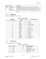
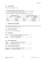
Page 29: ...No Link Off No activity Amber 10 Mbps Amber Half Duplex Green 100 Mbps Green Full Duplex 1 4 PRODUCT SPECIFICATIONS This section details the specifications for the Wayside Access Gateway For examples of wiring other equipment to the WAG see Section 2 1 4 1 Physical Specifications Standard 19 rack mount using relay rails 1 4 2 Dimensions H x W x D H 9 75 include mounting tab W 2 25 D 7 5 24 77 cm x...

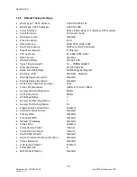
Page 30: ...ask 255 255 255 255 Radio Site ID Bindings No Bindings Configured WAG Circuit ID 000 0 00 Disabled Routing Region Domain 1 Disabled Routing Region Domain 2 Disabled ATCS Server UDP Port Number 5361 Telnet Port Numbers WAG 23 Serial 10023 Genisys Wait Poll Response 800ms ATCS Retry Wait 800ms ATCS Max Retrys 3 Genisys Poll Starting Station 1 Genisys Poll Ending Station 16 Fragile Telnet Connections...

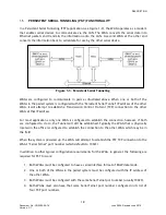
Page 31: ...ion to the other WAG at that IP address For most applications only one WAG is configured to establish the connection however if both are configured to do so the Tunnel will still be established Typically the WAG that is physically located in the office is configured to establish the connection to the other WAG which may be in the field When the system is powered up the WAG will attempt to establis...

Page 32: ...ONALITY When used in an Office System Interface OSI application see Figure 1 4 the WAG operates as a message router between the office system and field devices operating on the LAN Refer to the diagram below for the following discussion Ethernet Office system WAMS WAG SEAR II Echelon Other devices IP Network Ethernet Figure 1 4 Office Systems Interface The SEAR II SEAR IIi sends an ATCS message to...

Page 33: ...any pending LLLs the WAG will move the pending entries into the active list and any pending ATCS message is sent to the office At that time the timer for the pending entry is marked as Expired and the timer for the newly created active entry is started If no activity for an LLL in the Active route links list is seen before the timer counts down to the end the WAG will issue another route request f...

Page 34: ...ch are shipped from the factory as un jumpered These jumpers are used to connect the serial interface s Transmit and Receive signals together On the serial interface when J1 J2 are in place pins 2 and 3 on J1 transmit and receive are tied together to form half of the balanced wire signaling Pins 14 and 16 on J1 secondary transmit data and secondary receive data are tied together to form the second...

Page 35: ...emove the jumpers the operator may Telnet into the WAG to perform the configuration The operator must know the WAG s IP address 1 8 EXTERNAL J1 J2 JUMPERS The use of the J1 J2 Jumpers on the hardware can be moved off of the PC board and on to the connector plugged into the WAG s serial interface This way the operator need never open the WAG to remove jumpers in the event he or she wants to access ...

Page 36: ...er Test It s followed by the IP address of the WAG which is then followed by an X to indicate the end of the test frame 1 10 RS485 OPERATION When the WAG is configured for RS485 the WAG also must be configured for one of the Genisys ATCS protocols Office if the WAG is to operate as a Bus Master or Field if the WAG is to operate as a Bus Slave There must be only one WAG Bus Master configured as Gen...

Page 37: ...nector 2 Connector 3 p i n 2 p i n 1 4 p i n 2 p i n 1 4 p i n 2 p i n 1 4 Figure 1 7 RS485 Cable Interconnections Connector 1 Connector 2 Connector 3 p i n 2 p i n 3 p i n 1 4 p i n 1 6 p i n 2 p i n 3 p i n 1 4 p i n 1 6 p i n 2 p i n 3 p i n 1 4 p i n 1 6 Figure 1 8 RS485 Cable Interconnections ...

Page 38: ... to be sent and received on the serial interface Such ATCS messages are routed according to the message s ATCS destination address after their HDLC headers are removed The HDLC Raw Serial Tunnel mode of operation requires that the Persistent Serial Tunnel functionality be enabled When the Tunnel is established all forms of HDLC frames are sent and received on the serial interface complete with the...

Page 39: ...ng the mounting tab and holes on the back of the unit the WAG can be mounted on a standard 19 rack or shelf using standard relay rails The mounting holes accept standard 10 mounting screws After mounting the unit needs to be wired to the power supply The WAG may also be wall mounted 2 2 2 Wiring Wire power to the connector on the WAG as follows 1 Remove the supplied plug from the J4 connector WARN...

Page 40: ...WIRING TO OTHER EQUIPMENT 3 Wire the WAG to equipment that will be used With the exception of J3A use standard RJ45 connectors 2 3 EQUIPMENT CONNECTION TO WAG There are numerous pieces of equipment that can be connected to the WAG This section serves as a guide for connecting various devices to the WAG 2 3 1 Connecting to Safetran Ethernet Radio A53325 The following diagram shows the Safetran Ethe...

Page 41: ...N AND CONFIGURATION 2 3 Document No COM 00 05 16 June 2006 Revised June 2014 Version C 1 2 3 2 Connecting to an Ethernet Hub The following diagram shows an Ethernet hub connected to the WAG Figure 2 2 Ethernet Hub ...

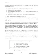
Page 42: ...2006 Revised June 2014 Version C 1 2 3 3 Connecting to an Ethernet Hub and Safetran Ethernet Radio A53325 The following diagram shows an Ethernet hub and a Safetran Ethernet Radio A53325 connected to the WAG Figure 2 3 Ethernet Hub and Safetran Ethernet Radio A53325 ...

Page 43: ...ION 2 5 Document No COM 00 05 16 June 2006 Revised June 2014 Version C 1 2 3 4 Connecting Two Sites Using Modems The following diagram shows connecting two sites using a pair of modems Figure 2 4 Connecting Two Sites Using Modems ...

Page 44: ...e or use a null modem adapter 2 Match the PC laptop COM port settings to the WAG serial port default settings Use the following table Table 2 1 PC Serial Port Settings Item Setting Baud 9600 Data bits 8 Parity None Stop Bits 1 Flow Control None NOTE If it is necessary to reset the WAG to the default configuration remove the WAG cover and hold down the S3 button mounted on the board before performi...

Page 45: ...laptop into the WAG cycle power on the WAG and tell the WAG that the executive should ignore the configuration options and execute with internal clocks in RS232 mode and in Command Mode Figure 2 6 WAG Terminal Emulation Boot With Number 7 Screen After 5 seconds and without the operator selecting a menu option Figure 2 5 is replaced with the screen in figure 2 7 NOTE If the screen shown in figure 2...

Page 46: ...nal Ready Screen 4 With the computer connected to the WAG and the terminal emulation software running type con and press ENTER to modify the WAG configuration settings The following screen appears Figure 2 8 HyperTerminal Configuration Screen To configure the WAG go to the Configuration of the WAG Section see Section 2 6 ...

Page 47: ...sk do not allow access to the WAG configured IP address 1 Open Telnet software 2 If this is the first time connecting to the WAG go to 10 232 53 40 port 23 If this is not the first time connect to the previously specified IP address for the unit NOTE The Telnet session is dropped after configuration changes have been saved If the WAG has been reconfigured the IP address may not be 10 232 53 40 Whe...

Page 48: ...ersion C 1 Select NEXT configuration menu for the Second Configuration Menu see Figure 2 10 Select NEXT configuration menu for the Third Configuration Menu see Figure 2 11 Refer to paragraph 2 6 for WAG configuration Figure 2 10 Second Configuration Menu Figure 2 11 Third Configuration Menu ...

Page 49: ... 3 addresses Changing the Type 7 ATCS address lets the user specify the Type 7 ATCS address for the WAG on the network The Type 7 address for each unit uses the field wayside equipment ATCS address format 7 RRR LLL GGG SS DD The address segments are as follows RRR The railroad number LLL Line Segment designation GGG A unique number for each group within that line segment SS Sub node Field used to ...

Page 50: ... returned to the First Configuration Menu The new Type 7 ATCS address is displayed 3 Prior to exiting the First Configuration Menu select Save changes then restart to save the changes and restart the WAG 2 6 2 Type 3 ATCS Address The WAG can be assigned both Type 3 and Type 7 ATCS addresses This enables the WAG to handle any ATCS message of either type that it sees See paragraph 2 6 1 for directio...

Page 51: ...hed the user will be returned to the First Configuration Menu The new Type 3 ATCS address is displayed 3 Prior to exiting the First Configuration Menu select Save changes then restart to save changes and restart the WAG 2 6 3 Serial Port Interface The user can make changes to the serial interface baud rate configure the number of data and stop bits on the serial interface enable or disable the flo...

Page 52: ... 4 To enable the changes select Accept current values When finished the user will be returned to the First Configuration Menu The new serial interface settings are displayed 5 Prior to exiting the First Configuration Menu select Save changes then restart to save changes and restart the WAG 2 6 4 Serial Format Changing the serial format can be selected from the following communication protocols RAW...

Page 53: ...f either Genisys ATCS protocol Office or Field any attempt to establish a TCP connection to the Serial Telnet port will be disallowed Such a connection attempt will cause the TCP connection to be established and then immediately be disconnected The TCP connection is allowed for a brief period of time to log that a connection was attempted and disconnected TCP connections are disallowed to the WAG ...

Page 54: ...ns are not allowed to the serial interface if there is no persistent tunnel This prevents an operator from interfering with any HDLC communications that are taking place on the serial interface Figure 2 16 An Example of HDLC Tunneling 2 3 4 1 5 17 24 2 3 3 2 2 Cable 1 Cable 2 RJ45 DB25 DB25 DB25 14 16 14 16 24 18 24 18 17 9 17 9 7 7 WAG BCM WAG Packet Switch Figure 2 17 An Example of HDLC Tunnelin...

Page 55: ...ion Menu select Echelon address to be changed The Change Echelon Address configuration screen appears prompting for the subnet address first two digits of Echelon address Figure 2 18 Echelon Configuration Screen 2 Do the following a To keep the current subnet address value press ENTER To enter a new value type the two digits of the new Echelon subnet address and press ENTER NOTE Set the subnet fie...

Page 56: ...ently UDP port numbers 9999 and 10000 are protected The user cannot specify these port numbers To Assign UDP Port Numbers 1 On the First Configuration Menu select UDP ports assignments to be changed The UDP port assignment screen appears The UDP port assignment defaults are 5000 5001 5002 and 5003 Figure 2 19 UDP Port Assignment Screen UDP Port Assignment Screen 2 To keep the current UDP port assi...

Page 57: ... 2 To keep the current displayed value press ENTER To enter a new value type the number of seconds desired NOTE The routing table is cleared with every power cycle of the WAG regardless of the timer value When finished the user will be returned to the First Configuration Menu The Route Table Expiry timer setting is listed 3 Prior to exiting the First Configuration Menu select Save changes then res...

Page 58: ...ed messaging is to be used by the WAGs to communicate across the Ethernet Both WAGs must have the same port number configured for serial Telnet TCP port numbers 9999 and 10000 are protected The user cannot specify these port numbers To Assign TCP Port Numbers 1 On the First Configuration Menu select TCP ports assignments to be changed The TCP configuration screen appears The TCP port assignment de...

Page 59: ...hen restart to save changes and restart the WAG 2 6 11 DHCP Server The Dynamic Host Configuration Protocol DHCP server or Site ID can be enabled or disabled depending on whether the WAG is required to provide configuration information for up to five A53325 Safetran Ethernet Radios When DHCP is enabled the WAG will support the A53325 Safetran Ethernet Radio operation running Linear Network Software...

Page 60: ...e user should ensure that a unique IP address is used for each unit on the network The default WAG IP Address is 10 232 53 40 Prior to starting ensure the user has available the complete IP address to be used To Assign WAG IP Address 1 On the First Configuration Menu select WAG IP Address to be assigned The Change WAG IP Address screen displays Figure 2 24 Change WAG IP Address Screen 2 To keep th...

Page 61: ...rs communicating as well as the device s interface If the device was heard on the Ethernet interface the IP address of the device that sent the ATCS message is recorded If the interface was Echelon the Subnet Node or Unique Neuron ID of the ATCS device is recorded This configuration setting tells the router how many digits to use when searching the destination ATCS address of a message against the...

Page 62: ... the number of bits from 8 to 32 and then press ENTER The user will be returned to the First Configuration Menu The Type 7 Address Route Length is displayed 3 Prior to exiting the First Configuration Menu select Save changes then restart to save changes and restart the WAG 2 6 15 Radio Site ID Bindings When the WAG is enabled to be a DHCP Server the WAG can provide A53325 Ethernet Communications R...

Page 63: ...re 2 27 Radio Site IDs DHCP Bindings Screen 2 Select one of the five bindings to create or to edit binding 1 for this description When the first binding is selected the DHCP Binding 1 screen appears Figure 2 28 DHCP Binding Screen The Binding IP Address is the address sent to the radio The radio will configure to the IP address as its own 3 To assign an IP Address to a Binding select IP Address on...

Page 64: ...he user will be returned to the DHCP Binding Screen 5 Select change binding Left transmit channel The Change Binding Left Transmit Channel screen appears Figure 2 31 Change Binding Left Transmit Channel Screen 6 To keep the transmit channel default press ENTER If not enter the transmit channel from 3 to 37 and then press ENTER The user will be returned to the DHCP Binding Screen 7 Select change bi...

Page 65: ...d default press ENTER If not select the option number for the desired transmit speed and then press ENTER The user will be returned to the DHCP Binding Screen 11 Select change binding Left receive channel The Change Binding Left Receive Channel screen appears Figure 2 34 Change Binding Left Receive Channel Screen 12 To keep the left receive channel default press ENTER If not select the channel num...

Page 66: ...wer Screen 16 To keep the transmit power default press ENTER If not enter the transmit power from 0 to 23 and then press ENTER The user will be returned to the DHCP Binding Screen 17 Select change binding Right transmit speed The Change Binding Right Transmit Speed screen appears Figure 2 37 Change Binding Right Transmit Speed Screen 18 To keep the transmit speed default press ENTER If not select ...

Page 67: ...e changes 23 To exit without making a change select Exit without saving changes 24 To delete the binding entirely select delete this binding 25 Prior to exiting the First Configuration Menu select Save changes then restart to save changes and restart the WAG After a binding has been configured the following is displayed on the Radio Site IDs DHCP Binding screen Figure 2 39 Radio Site IDs DHCP Bind...

Page 68: ...an IP address it would like to have assigned it will ask the WAG for that IP address otherwise the radio is not configured and does not offer an IP address hint informing the WAG that it has no preference The WAG will receive the configuration request and will examine the hardware MAC address of the radio and any IP address hint the radio might have offered and then check its configured bindings t...

Page 69: ...ill ignore the DHCP request from that radio Site installation of radios with DHCP configuration is important to install and configure properly Whether it is the simple installation of one radio and one or more WAGs or more complex with multiple radios and one DHCP serving WAG the WAG has the ability to trace DHCP requests and replies Additionally the diagnostic command status offers information ab...

Page 70: ...t WAG Circuit ID to be changed The Change WAG Routing Region screen appears Figure 2 42 Change WAG Routing Region Screen Initial Screen 2 From this initial screen Figure 2 42 do one of the following a To leave the three digits of the first field of a currently assigned WAG Circuit ID unchanged press ENTER Go to step 3 b To change the three digits of the first field of the WAG Circuit ID type the d...

Page 71: ...ure 2 44 Change WAG Routing Region Screen After Digits Entered In Second Field 5 Prior to exiting the First Configuration Menu Save changes then restart to save changes and restart the WAG 2 6 18 Routing Region Domain 1 Routing Region Domain 1 consists of four data fields and is intended to contain an IP address if the first field is set to 0 the function is disabled The IP address can be a single...

Page 72: ...then press ENTER Go to step 4 c To disable Routing Region Domain 1 select Disable Routing Region Domain One and then press ENTER The user is returned to the Second Configuration screen d To exit this function without making changes select Exit without a change and then press ENTER The user is returned to the Second Configuration screen 3 From the screen in figure 2 45 If Enter an IP Address was se...

Page 73: ...anges and restart the WAG 2 6 19 Routing Region Domain 2 Routing Region Domain 2 is identical to Routing Region Domain 1 described in paragraph 2 6 18 above If this function is configured with a valid IP address copies of every route request message the WAG sends will be transmitted out this IP address as well as Domain 1 Two domains are provided in the event a router is located somewhere on the L...

Page 74: ... new port number and then press ENTER Entry can be any value from 0 to 65535 The user will be returned to the Second Configuration Menu 3 Prior to exiting the First Configuration Menu select Save changes then restart to save changes and restart the WAG 2 6 21 Telnet Port Numbers Because there are routers bridges and hubs that block Telnet port 23 for security reasons the well known Telnet and Seri...

Page 75: ...enter the new WAG Telnet Port Number and then press ENTER Entry can be any value from 0 to 65535 The default is 23 Figure 2 50 Change WAG Telnet Port Number Screen 4 From the screen in figure 2 51 press ENTER to keep the current port number or enter the new Serial Telnet Port Number and then press ENTER Entry can be any value from 0 to 65535 The default is 10023 Figure 2 51 Change Serial Telnet Po...

Page 76: ...Timer screen appears Figure 2 52 Change Genisys Poll Response Wait Timer Screen 2 To keep the current timer setting press ENTER To change the timer setting enter the new value and then press ENTER Entry can be any value from 20 to 65535 The user will be returned to the Second Configuration Menu 3 Prior to exiting the First Configuration Menu select Save changes then restart to save changes and res...

Page 77: ...rface is configured for Genisys ATCS Office It designates the number of times to retry the sending of an ATCS message before giving up after waiting for an acknowledgement The default value is 3 To set the ATCS Max Retries value 1 On the Second Configuration Menu select ATCS Max retries count to be set The Change Genisys ATCS Maximum Retry Count screen appears Figure 2 54 Change ATCS Retry Timeout...

Page 78: ...mber Screen 2 To keep the starting station number setting press ENTER To change the starting station number setting enter the new value and then press ENTER Entry can be any value from 0 to 64 The user will be returned to the Second Configuration Menu 3 Prior to exiting the First Configuration Menu select Save changes then restart to save changes and restart the WAG 2 6 26 Genisys Poll Ending Stat...

Page 79: ...lse attempts to make a connection the old connection is dropped in favor of the new one allowing a user to steal the connection When the Fragile Sockets function is disabled if a Telnet or Serial Telnet connection exists and someone else tries to make the connection the attempted connection is refused and the original owner keeps the connection The Fragile Sockets function defaults to ENABLED so t...

Page 80: ...al Tunnel Telnet IP Address or Symbolic Name to be changed The Change Persistent Serial Telnet IP Address screen appears Figure 2 58 Change Persistent Serial Telnet IP Address Screen 2 Do one of the following a To change or enter the IP Address select Enter an IP address option number and press ENTER Go to step 3 b To change or enter the Symbolic Name select Enter a Symbolic name option number and...

Page 81: ...will be returned to the Second Configuration Menu Go to step 5 Figure 2 59 Change Persistent Serial Telnet IP Address Screen 4 On the screen in figure 2 60 enter the symbolic name for the Persistent Serial Telnet IP Address Entries can consist of up to 40 characters including A Z 1 9 and 0 periods and dashes After entering the symbolic name press ENTER The user will be returned to the Second Confi...

Page 82: ...tent Serial Tunnel 000 0 00 Disabled Disabled Disabled 5361 WAG 23 Serial 10023 800ms 800ms 3 1 16 Enabled 010 232 053 043 2 6 29 Primary and Secondary DNS These are the IP addresses of one or two DNS servers that are somewhere on the user s WAN If the Domain One Domain Two or Default Gateway for the WAG is configured to use symbolic names rather than hard coded IP addresses either the primary DNS...

Page 83: ... loss of the office links by timing out the Active then Pending routes and then discarding the resolved IP addresses which may or may not be valid any longer Then the WAG after discarding the old resolved IP addresses will again ask the DNS servers what the IP addresses are for the symbolic names In the event a user reconfigured the IP address for the symbolic names in the DNS servers the servers ...

Page 84: ...ng a To disable the Secondary DNS IP Address enter 0 zero in the first data field and then press ENTER The user will be returned to the Second Configuration Menu Go to step 3 b To leave the first data field of the current IP Address unchanged press ENTER c To change the first data field of the IP Address type the digit s and then press ENTER Entry can be any value from 1 to 255 d Repeat step b or ...

Page 85: ...ault IP Gateway Address to be changed The Change Default Gateway IP Address screen appears Figure 2 63 Change Default Gateway IP Address Screen 2 From the screen in figure 2 63 do one of the following a To disable the Default Gateway IP Address enter 0 zero in the first data field and then press ENTER The user will be returned to the Second Configuration Menu Go to step 3 b To leave the first data...

Page 86: ...fter entering the site name press ENTER The user will be returned to Third Configuration Menu 3 Prior to exiting the First Configuration Menu select Save changes then restart to save changes and restart the WAG 4 Following the save the WAG Site ID can be viewed using the SCON command to show the current configuration 2 6 32 Route RAW Echelon No In previous executive software releases for the WAG R...

Page 87: ...first In previous releases of the executive software WAG would go ahead and route Echelon messages out its Echelon interface even if the destination ATCS device wasn t in its route table When this field is configured as YES the WAG will continue to route Echelon messages for devices it hasn t seen yet out its Echelon interface When this field is configured as NO the WAG will not route Echelon ATCS...

Page 88: ... to the WAG If a password is required any time the operator enters a command yet hasn t offered the password yet the command that was entered will be ignored If the operator persists in entering commands every third attempt the operator will be asked to offer the Telnet Password The WAG defaults this configuration setting to DISABLED Figure 2 67 Telnet Password Option 2 6 35 RS485 J1 J2 Jumper Det...

Page 89: ...eqip Request a new IP address from a DHCP server Restart res Reboots the WAG Revisions rev Displays all WAG software version information Routes rou Shows the route table Rping rpi Pings a route ID Sconfig sco Shows current configuration settings Smac sma Shows MAC addresses in the route table Status sta Displays status information of system operation Sdate sda Sets the current date Stime sti Sets ...

Page 90: ...s 9178 released 55 in use Memory OKAY 314784 free 313292 largest Sequence 2 Serial channel Sent 120 frames received 21 frames 116 transmit chokes encountered Serial interface max baud 115200 Router status 3003 messages routed Entity Echelon 00000000 from 00000000 to Entity Serial 00000000 from 00000000 to Entity XPort 00003003 from 00000000 to Entity Unknown 00000000 from 00000000 to Local routes ...

Page 91: ...2 24 stack use Run Queue task_serial_out 03 04 11 stack use Run Queue task_xport_out 07 08 15 stack use Run Queue task_app_timer 08 09 12 stack use Delayed task_led 00 01 15 stack use Delayed task_echelon_out 05 06 12 stack use Mailbox task_serial_in 02 03 18 stack use Other Que task_echelon_in 04 05 13 stack use Other Que task_xport_in 06 07 39 stack use Other Que task_router 09 10 44 stack use O...

Page 92: ...he LLL of 112 It also indicates that it is the computer where Network Management System messages may be sent Region 9999 is a special region number indicating Network Management Entries in the Pending route links section indicate which routes are waiting for an office device to express interest in them The example shown above indicates that WAG has ATCS traffic from two devices one with an LLL of ...

Page 93: ...ation appears similar to the following smac IP Address Hardware MAC address ATCS Address 010 232 053 041 00 20 4a 81 e7 40 7 620 020 020 03 02 010 232 053 041 00 20 4a 81 e7 40 7 620 020 020 03 03 010 232 053 041 00 20 4a 81 e7 40 7 620 123 123 12 10 3 5 VIEWING THE WAG CONFIGURATION This command shows the current configuration settings for the WAG To View the Configuration Type sconfig and press ...

Page 94: ...re is no Tunnel established and there is no Persistent Serial Tunnel IP address configured into the WAG the user may manually request a for the duration tunnel to a remote WAG by typing tun followed by the IP address of the remote WAG For example if the user types tun 10 232 53 55 The WAG will show Attempting Serial Tunnel to 10 232 53 55 This for the duration tunnel requires that both WAGs have t...

Page 95: ... run time messages out the serial interface when the serial interface is in Command Mode Each run time message is assigned a verbosity level at which it is displayed The allowable verbosity levels are 0 through 65534 however only 1 through 10 are significant 1 No logging of diagnostic information 10 Enables the logging of diagnostic information regarding multipart ATCS messages To Change the Verbo...

Page 96: ...stic command that is very useful for determining whether a communications path exists between the WAG and an office system To Use the Route Ping Command Type rping followed by a route region number and then press Enter For example if a user wants to know whether the WAG can talk to AServer in the office the user can type rping 9999 NOTE 9999 is the special Route Region number that means Network Ma...

Page 97: ...networks which may include radios responses could take more than 10 seconds to be received and displayed by the WAG 3 11 TRACING AN INTERFACE The Trace command allows tracing of several interfaces The user must specify an option after the Trace command or the following will be displayed The user can enable or disable a trace of one interface at a time This is accomplished by typing either X E S P ...

Page 98: ...be sent out the Ethernet interface To Trace an Echelon Interface The tracing of Echelon information will go out both the serial interface and to a Telnet session if one is running Type trace E and then press Enter The Echelon information begins as follows trace E Echelon activity will trace to serial port and Telnet To Trace a Serial Interface The tracing of Serial information will only be sent to...

Page 99: ...9397be1 Client IP 000 000 000 000 Your IP 000 000 000 000 Client MAC 00 0d 94 00 3a c2 Remaining options Option 053 35 length 001 bytes 001 Discover Option 055 37 length 006 bytes 001 002 003 00c 03c 02b Option 051 33 length 004 bytes 000 009 03a 080 DHCP Sending ping 0x4dd8 to 10 232 53 53 Inbound DHCP Request Ethernet MAC length 6 hops 0 Transaction 3bfclab0 Client IP 000 000 000 000 Your IP 000...

Page 100: ...s within that radio To Trace Office System Interface to Serial and Telnet The Trace Office System Interface to Serial and Telnet option is for debugging purposes Type trace I and then press Enter The Office System Interface to Serial and Telnet information begins as follows trace I Office activity will trace to serial port and Telnet When tracing is enabled for the Office System Interface the foll...

Page 101: ...mote Ech NO indicates that the remote WAG is considered to not have any Echelon clients IPR Indi Remote OK YES Active YES Remote Ech YES This indicates that the WAG is sending an Indication message to its Ladder Logic device and that the remote WAG is in communication with the WAG being traced the WAG is also Active Primary and that the remote WAG has Echelon clients in its route table IPR Ctrl Go...

Page 102: ...hat the operator can request Each trace has an accompanying timestamp so that it is easier for an operator to see when things happen 3 12 SETTING THE CURRENT DATE The sdate command provides the WAG the current date If the user types the sdate command without any arguments the WAG will display the acceptable syntax for setting the current date Type sdate followed by the date in DD MM YY format and ...

Page 103: ...s showing the interface is in Command Mode To go to Data Mode if the serial interface is configured for a data protocol Type data and press Enter NOTE Configuration changes are made with the WAG in Command Mode If the user makes configuration changes and saves those changes the WAG will restart with the new configuration but will come up in Data Mode if the serial interface is configured for a ser...

Page 104: ...s Fixed Buff Remaining 0x104 260 bytes System Log start 0x7D330 System Log end 0x7FB30 10240 bytes 102 lines Unallocated Heap start 0x7FB50 Unallocated Heap end 0x80000 1200 bytes Executable start 0x230004 Executable end 0x24B40A 111622 bytes System run time 0 days 18 H 13 M 55 S NOTE The Current Date Time will be displayed if the date and time has been set otherwise the time elapsed since the WAG...

Page 105: ... 010 232 053 040 00 00 01 24 TCP 010 232 053 025 on port 23 Connected 00 00 01 26 CONFIG command received 00 00 01 37 TCP 010 232 053 025 on port 23 Disconnected 00 00 02 23 Route Drop 7 620 020 010 03 02 00 00 02 26 TCP 010 232 053 025 on port 6001 Connected 00 00 02 26 TCP 010 232 053 025 on port 6002 Connected 00 00 02 26 Route Drop 7 620 020 020 03 03 00 00 02 27 Route Drop 7 620 020 020 03 02...

Page 106: ...ret 00232C7C 00 01 35 07 D0 00200000 A0 00100000 00 01 35 07 D1 00200001 A1 00100001 00 01 35 07 D2 00200002 A2 00100002 00 01 35 07 D3 00200003 A3 00100003 00 01 35 07 D4 00200004 A4 00100004 00 01 35 07 D5 00200005 A5 00100005 00 01 35 07 D6 00200006 A6 00100006 00 01 35 07 D7 00200007 A7 000575DE 00 00 00 00 Wayside Access Gateway Started 00 00 00 00 Route Add Echelon 001 003 type 41 7 620 020 ...

Page 107: ...Siemens Rail Automation personnel for troubleshooting Fatal ERROR Memory address x invalid Indicates that a programming error occurred Used by Siemens Rail Automation personnel for troubleshooting Fatal ERROR Ser no RX buf A flood of inbound serial data occurred that the WAG could not handle properly Used by Siemens Rail Automation personnel for troubleshooting Fatal ERROR Ser out exceeded x Used ...

Page 108: ...n t write application sectors There is a problem with writing FLASH ROM Warning ERROR ECH RX Not first Used by Siemens Rail Automation personnel for troubleshooting Warning ERROR Ser RX Not first Means that a serial interface error occurred Used by Siemens Rail Automation personnel for troubleshooting Warning ERROR Ser TX Not first Means that an outbound serial message was attempted to be transmit...

Page 109: ... configuration and then makes this log entry before it starts operating Warning WARNING Echelon device shares our Echelon address Means that the WAG discovered an Echelon device on the Echelon interface which has the same subnet and node address as itself Correct the problem by reconfiguring either the WAG Echelon address or by reconfiguring the Echelon address of the other device Warning WARNING ...

Page 110: ... Automation personnel for troubleshooting Warning Warn Echelon4 ignore diag Used by Siemens Rail Automation personnel for troubleshooting Warning Warn Echelon5 unsupported APDU address format Used by Siemens Rail Automation personnel for troubleshooting Warning Warn Echelon6 unsupported TPDU address format Used by Siemens Rail Automation personnel for troubleshooting Warning Warn Echelon8 unsuppor...

Page 111: ... to send executive code to the WAG however the WAG determined the code was not WAG executive code so the file was not saved Informational TEST err x box y time z Indicates that a programming error occurred Used by Siemens Rail Automation personnel for troubleshooting Informational FLASH New boot code saved Indicates the user successfully used the XFILES command to send new boot code to the WAG The...

Page 112: ...he WAG is done with a test Informational Performing factory test mode Someone requested a factory test either from the serial interface or from a Telnet session Informational Performing screen test mode Someone requested a factory serial port screen test either from the serial interface or from a Telnet session Informational Performing spew test mode Someone requested a factory spew test either fr...

Page 113: ... add Means an ATCS address of a routable device that has been removed from the WAG route table The entry expired If the device was on a TCP connection the TCP connection has been disconnected Informational Route Drop UNID neuron ID Means an Echelon device that is addressed with a Unique Neuron Identifier address has been removed from the WAG routing table because it expired Informational Service b...

Page 114: ...nged Indicates that the user requested configuration and either exited without making or saving any changes Informational CONFIG Configuration has been changed Indicates that the user made configuration changes to the WAG Informational CONFIG Radio binding x yyy yyy yyy yyy has been changed Indicates that the IP address of a particular binding from 1 to 5 inclusive was changed by the user Informat...

Page 115: ...heard drops out of communication and doesn t respond after 30 seconds the fact that the station was dropped gets logged Informational WAGs Report In request was issued When the WAGREPORT command is issued described later this system event is logged by the WAG that issued the request Informational Responded to WAGs Report In request When another WAG on the LAN is used to issue a WAGREPORT command d...

Page 116: ...ASH ROM Configuration then the WAG will restart After the WAG restarts it will take approximately 30 to 40 seconds for the new configuration to be established in the WAG s XPORT component REQIP via Service Button The operator may hold down the S3 Service Button mounted on the PC board of the WAG for 10 seconds and once the button is released the WAG will issue a DHCP Request just like it s done wh...

Page 117: ...ecuting the various tasks in the WAG The command is intended to be used by Siemens Rail Automation engineering during development however installers and maintainers might find the information informative The amount of time that the WAG spends idle and not performing any other task s functions is a good indication as to how busy a WAG is Typically WAG s idle times will be greater than 80 The number...

Page 118: ...er information about the software running in the WAG Xilinx Checksum 0x52D7F8AF Name XIL_DATA 9V858 A01C Ver 1 4 Boot Monitor CRC 0x11B25884 Version 9V841 A01E1 Test Date May 30 2006 Executive CRC 0x92FA3BD4 Version 9V842 A01E1 Test Date May 30 2006 16 27 11 XPORT Checksum 0x224F0000 Version 9V846 A01E0 Date Mar 24 2006 13 01 06 Configuration Version 2 ...

Page 119: ... an Ethernet LAN and they can be configured to communicate not communicate or to form subgroups of WAGs An example of this is six WAGs on the Ethernet LAN two of which use a UDP Slot 1 port number of 6100 while the other four use UDP Slot 1 port number 9420 The two subgroups cannot communicate to the other The WAG in each subgroup can communicate among themselves Check the UDP port number configur...

Page 120: ...erial interface in Command Mode to see the route being added and dropped repeatedly To solve the problem increase the route table expiry timer The Type 7 address route length configured into the WAG may not be what the site installer intended For example if the route length is configured for 10 digits 7 RRR LLL GGG then all ATCS addresses that share the same RRR LLL and GGG will have a single entr...

Page 121: ... following for LED information Link LED Top of J2 Activity LED Bottom of J2 Color Meaning Color Meaning Off No Link Off No activity Amber 10 Mbps Amber Half Duplex Green 100 Mbps Green Full Duplex NOTE The configurable network subnet mask bits and the IP address of all devices should be checked See Section 2 for information on configuration of the IP network mask Verify that all devices that netwo...

Page 122: ...ty is correct The power connector can be faulty either a broken connector or the wires to the connector are broken or shorted Use a voltmeter at the B N pins to verify that the power is getting to the pins It is possible that the hardware is damaged such that the DC to DC converter inside is not working Because the LED is hard wired to be ON when power is applied if power is good at the B N pins a...

Page 123: ...e problem is a faulty serial cable Always use a simple null modem serial cable with at least three conductors Transmit Receive Signal Ground The Transmit and Receive signals should be crossed between the computer and the WAG If the user performs both of the above items and still cannot see the boot menu perform a default configuration request Do the following 1 Carefully open the WAG 2 Locate the ...

Page 124: ...ow on a computer that is also connected to the same Ethernet LAN that the WAG is connected to NOTE Before pinging WAG verify that the computer subnet address matches that of the WAG Perform a PING command If PING does not get any responses there is a bad Ethernet cable a bad Ethernet connection or perhaps a bad Ethernet radio switch hub or router or possibly a firewall is interfering Evaluate thos...

Page 125: ...figured to correct the problem the WAG power must be cycled to reset the problem reporting It is possible there is a shared IP address even if the user does not see it in the routing table Examine the configuration of all WAGs on the Ethernet LAN To help isolate the problem WAG open a DOS window on a computer connected to the same Ethernet LAN and PING the suspect IP address Now power down each WA...

Page 126: ...TROUBLESHOOTING 4 8 Document No COM 00 05 16 June 2006 Revised June 2014 Version C 1 This page intentionally left blank ...

Page 127: ...thod is described in this section 5 2 DOWNLOADING SOFTWARE TO WAG USING XFILES COMMAND NOTE The xfiles command is to be used only with the serial interface If the user attempts to run this command via Telnet sessions the file transfer will fail 1 Type xfiles and then press Enter The ZMODEM file transfer menu will be displayed Figure 5 1 ZMODEM File Transfer Menu 2 From the ZMODEM file transfer men...

Page 128: ...e transfer protocol to Zmodem and then click Send The Zmodem File Send screen will be displayed Figure 5 3 Zmodem File Send Screen 6 When the download is complete restart the WAG 5 3 UPLOADING SOFTWARE FROM WAG USING XFILES COMMAND NOTE The xfiles command is to be used only with the serial interface If the user attempts to run this command via Telnet sessions the file transfer will fail ...

Page 129: ...ftware type to upload by choosing the applicable upload option Options 5 through 7 3 Waiting to send ZMODEM type of file is displayed on the file transfer screen 4 Select Receive file from the Transfer menu The Receive File pop up screen will be displayed Figure 5 5 Receive File Pop up Window 5 Select the file location of the software to be uploaded Set the file transfer protocol to Zmodem and the...

Page 130: ...her terminal emulator To download files to the WAG from the boot screen figure 5 7 follow the procedures described in paragraph 5 2 Figure 5 7 WAG Boot Screen After the new executive software is sent to WAG the WAG automatically stores the new software in FLASH memory If the update is not successful and the software was improperly stored or simply does not run properly the boot code remains unaffe...

Page 131: ...oot Options 1 Download Executive to WAG See Section 5 2 Download Configuration to WAG See Section 5 3 Download Xilinx to WAG See Section 5 4 Upload Configuration from WAG See Section 5 5 Run Debugger See Section 6 6 Run Executive Runs the executive software in the WAG 7 Run Executive internal clocks RS232 Command Mode Run if the WAGs serial interface is configured to utilize external transmit cloc...

Page 132: ...OLLOWING PROCEDURE SHOULD ONLY BE PERFORMED IF DIRECTED BY A SIEMENS RAIL AUTOMATION EMPLOYEE IF THIS PROCESS IS PERFORMED INCORRECTLY DAMAGE TO THE WAG CAN OCCUR To Debug from the Boot Menu 1 Restart the WAG Figure 6 2 Boot Options Screen 2 At the Choice prompt press 5 and then press Enter within five seconds At the next prompt type help and press Enter The list of available commands is displayed...

Page 133: ... Description mem Show Memory This command determines whether a RAM address has a hardware problem or determines if a particular FLASH ROM sector is empty Use this command only under the direction of a Siemens Rail Automation employee The MEM command takes either one or two arguments mem starting address in HEX optional number of bytes in decimal The contents of memory at the starting address are s...

Page 134: ...nto an area of FLASH ROM This command is useful for saving boot code Xilinx code configuration or executive code into an otherwise unused FLASH sector Typically the user will only use this command when directed by a Siemens Rail Automation employee Additionally the user can capture blocks of RAM and save them to otherwise unused FLASH ROM This command requires three arguments flash_program destina...

Page 135: ... the registers of the internal CPU with known values and then forces a fatal error to ensure that the accurate contents of the CPU registers are displayed in the event of an actual fatal error After the user types exception an example of the following diagnostic information is displayed Figure 6 4 Exception Test Diagnostic Information exit Exit debugger This command exits back to the Boot menu 6 4...

Page 136: ...are in FLASH memory CAUTION ENSURE THAT THE XILINX FILE IS VALID FOR WAG USAGE PRIOR TO UPGRADING THE WAG IF THE WRONG XILINX FILE IS LOADED THE WAG WILL BECOME INOPERABLE AND WILL NEED TO BE RETURNED FOR REPAIR Refer to Section 5 for the procedures to upgrade the WAG Xilinx software 6 5 TROUBLESHOOTING COMMANDS This section describes additional troubleshooting commands that can be used 6 5 1 Usin...

Page 137: ...display it out the serial interface The command accepts a single argument in decimal of the starting RAM address the XPort is required to dump When xdump 3240 is typed the following is displayed Figure 6 5 Xdump Block Display The XDUMP command always requests blocks of 128 however since XPort only maintains 64K of RAM if the operator requests a starting address closed to the end of RAM a partial b...

Page 138: ...USING ADVANCED OPTIONS 6 8 Document No COM 00 05 16 June 2006 Revised June 2014 Version C 1 This page intentionally left blank ...

Reviews: