7SG14 Duobias-M-200 Commissioning
Test currents of the following range are required:
The bias characteristic requires 2 sources to be applied simultaneously.
The sources must be capable of delivering at least 5 x the rated current of the relay terminal used.
If differential high-set settings greater than 4 x I
N
are intended to be tested then a larger current source will be
required. The basic test equipment for primary and secondary injection test is as follows:
A digital test set capable of at least 2 x three phase current injection. The set must be capable of injecting at least
4 x the rated current on any of the relay inputs. For relay models with voltage inputs the amplifiers need to be
reconfigured for voltage output.
500V insulation resistance test set.
Digital Multimeter
Laptop PC to drive the test set and the Reydisp Evolution relay software.
500volt Variac to measure CT magnetizing characteristics and inject the Restricted Earth Fault elements.
Primary test leads and injection set.
Suitable primary injection connectors, secondary injection test plugs, test leads and a suitable a.c supply may be
required. These must be suitable for the connections available at the site concerned.
When making secondary injection tests ensure that the test circuit is earthed at one point only. All trip and alarm
wiring must be isolated to ensure no unexpected tripping or alarms occur.
5 Insulation resistance test
The relay terminals are factory tested to 3.5kV rms for 1 second and therefore the relay itself does not requires a
pressure test. The external wiring must still be tested for any insulation breaks.
Before commencing a visual inspection of the wiring take the following precautions:
Isolate the auxiliary supplies
Remove the trip and inter-trip links
Check that the relay wiring is complete and that all terminal connections are tight and remove the earth links
before conducting insulation resistance tests.
Measure the insulation resistance between each section of the wiring and the other sections connected together
and to earth.
The sections comprise:
a)
CT secondary wiring connected to module AN 1
b)
CT secondary wiring connected to module AN 2
c)
Other optional CT and V.T. secondary winding connected to modules AN 3, 4 or 5.
d)
D.C. wiring connected to PSU and I/O modules, excluding power supply wiring to the PSU module.
Before testing the d.c. wiring to earth, apply test connections between suitable points to short circuit each status
input and series resistor to avoid possible damage to the opto-coupler should the wiring be earthed.
e)
Test the power supply wiring to module PSU separately. Note that the d.c. +ve and d.c. -ve are each
connected to earth by surge capacitors. This will lead to a slight drain current of 5 to 15mA.
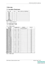
Record the results in Table 1.
Insulation resistance values that are considered satisfactory must depend upon the amount of wiring involved.
Generally, where a considerable amount of multi-core wiring is included, a reading of 2 to 3 mega-ohms is
reasonable but higher readings should be expected. A reading of 1M ohm should not normally be considered
satisfactory.
©2010 Siemens Protection Devices Limited
Chapter 7 Page 5 of 20


