7SG11 Argus Technical Reference
©2013 Siemens Protection Devices Limited
P20007 Page 65 of 71
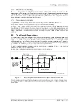
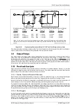
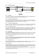
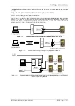
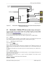
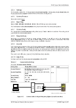
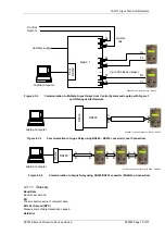
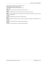
4.2.4 Network Topology
Communication networks can be connected either in star or ring format.
Laptop computer
P300007 Communications.vsd / Sigma 4 remote
R
S
2
3
2
Sigma 4
(SG4-103)
Tx
Rx
Tx
Rx
4.2.5 Settings
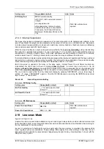
Communication parameters of
Communications Interface:
Comms Baud Rate
,
Communications Interface:
Comms Parity
and
Communications Interface
: Line Idle
should match those of the communicating device.
4.2.6 IEC Class II Measurands
Class II measurands can be sent as either ASDU 3 (reports 1 current channel) or ASDU 9 (reports 9 channels, Ia,
Ib, Ic, Va, Vb, Vc, P, Q), The values are returned as a fraction of a nominal value ie 1A, 63.5v. The
Communications
Interface:
IEC Class II Measurand
setting should be set as appropriate for each system.
4.2.7 IEC Class II Update period
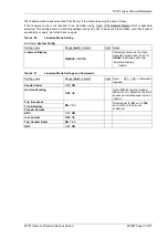
The class II measurand is updated in the relay at a period dependant on the
Communications Interface:
Class 2 Update
Period
setting. This ranges from instantaneous (constantly updated) to every 60s (updated every minute).
4.2.8 IEC Class II scaling
The measurands returned are fractions of nominal system quantities. The maximum range of the measurand can
be set either 1.2 or 2.4 times the nominal. Values that exceed this range will be returned as the maximum value
and flagged overflow. Note using 2.4 times scaling will double the range but half the resolution per bit. The
Communications Interface:
IEC Class II Scaling
setting should be set as appropriate for each system.
4.2.9 Baud Rate
Rates of
19200
,
9600
,
4800
,
2400
,
1200
,
600
,
300
,
150
,
110
and
75
bits per second are provided. However, only
19200
and
9600
are defined in IEC 60870-5-103, the additional rates are provided for local or modem communications.
The
Communications Interface:
Comms Baud Rate
setting should match that of the communicating device, e.g. P.C.
4.2.10 Comms Parity
IEC 60870-5-103 defines transmission as using
Even
parity, however, in some instances an alternative may be
required. The
Communications Interface:
Comms Parity
setting allows parity of
None
to be selected. This setting should
match that of the communicating device, e.g. PC.
4.2.11 Relay Address
Each relay on a network must have a unique address, between
1
and
254
, as set by the
Communications
Interface:
Relay Address
setting. A relay with the default address of
0
will not be able to communicate.
4.2.12 Line Idle
The IEC60870-5-103 protocol defines a line idle state of
Light On
. Binary ’0’ is represented by light on, binary ‘1’ is
represented by light off, and when a device is not communicating it idles with the light on (sending ‘0’). This allows
detection of a broken fibre condition. When the line is idling, a binary ‘0’ should be received constantly. If binary ‘1’
is received constantly, then no light is being received, hence the fibre may be broken.
The
Communications Interface
: Line Idle
setting must be set to be either on
or off
to be compatible with the
communicating device connected to the relay.


