On-Line Operation
UMSITRPDS3-1
November
2010
6-28
6.4.14 D/A Trim
There are two trim options: D/A trim and Scaled D/A trim. Since they operate similarly, only the D/A
trim is described here.
IMPORTANT
Trimming the D/A converter should not be necessary and should be performed
only after all other options have been exhausted.
1.
Remove the end cap from the enclosure terminal compartment. Connect a digital milliammeter to the
provided terminals.
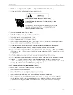
WARNING
Explosion can cause death or serious injury.
Only a certified ammeter may be used in intrinsically
safe circuits.
In a Division 1 area, where an explosion-proof rating is
required, remove power from the transmitter before
removing either enclosure cap.
2.
In the Online menu, press 3 Device Setup.
3.
In the Device Setup menu, press 2 Diagnostics/Service.
4.
In the Diagnostic/Service menu, press 4 Trim.
5.
In the Trim menu, press 3 Trim Analog Output.
6.
In the Trim Analog Output menu, press 1 D/A trim. A warning message will appear: “Loop should be
removed from automatic control.”
7.
The message “Connect reference meter” will appear; see step 1. The message “Setting field device
output to 4 mA” will appear. Press OK to continue. Type a new value and press ENTER. The
message “Field device output 4.000 mA equal to reference meter?” will appear. Press 1 Yes or 2 No.
If Yes is pressed, go to the next step. If No is pressed another opportunity to enter a new setting will
be provided.
8.
The message “Setting field device output to 20 mA” appears. Press OK to continue. Type a new value
and press ENTER. Press 1 Yes or 2 No. Press OK to store the value and return to the previous menu.
6.4.15 Transmitter Current Adjustment
The current output by the transmitter can be adjusted independent of the input pressure signal and
measuring circuit. This permits the output current to be adjusted to compensate for external inaccuracies,
for example, the +/-0.5% tolerance of a current-to-voltage conversion resistor where 4 mA must yield
exactly 1V and 20 mA must yield exactly 5V. These trims can be cancelled in the Diagnostics/Service
menu and factory set trims again installed.
Summary of Contents for 7MF4033 series
Page 48: ...Model 275 Universal Hart Communicator UMSITRPDS3 1 November 2010 2 26 ...
Page 86: ...Installation UMSITRPDS3 1 November 2010 4 34 ...
Page 152: ...Calibration and Maintenance UMSITRPSD3 1 November 2010 7 20 ...
Page 158: ...Circuit Description UMSITRPDS3 1 November 2010 8 6 ...
Page 197: ......
Page 198: ......
Page 200: ...Model Designations and Specifications UMSITRPDS3 1 November 2010 9 42 ...
Page 204: ...Glossary UMSITRPDS3 1 November 2010 10 4 ...
Page 208: ...Appendix A Online Configuration Map UMSITRPDS3 1 11 4 November 2010 ...
Page 216: ...Appendix C Elevation and Suppression Correction UMSITRPDS3 1 13 4 November 2010 ...


