8
05.01
8.9 Master/slave operation, SIMODRIVE 611
8-297
©
Siemens AG 2012 All Rights Reserved
SIMODRIVE 611 Configuration Manual (PJU) – 02/2012 Edition
8.9
Master/slave operation, SIMODRIVE 611
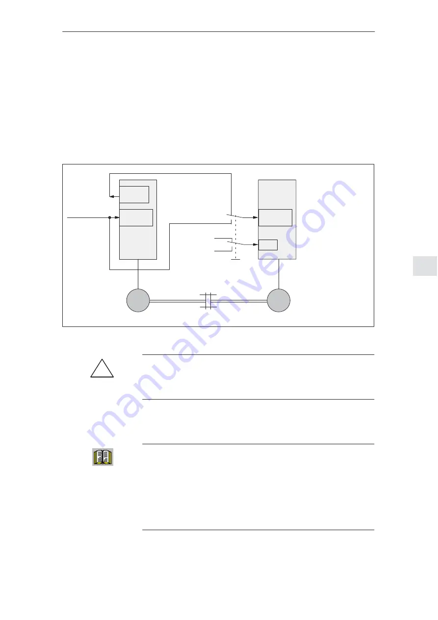
Two SIMODRIVE main spindle drives can be operated, rigidly and mechanically
coupled together if the master drive is closed–loop speed controlled and the
slave drive is closed–loop torque controlled.
The application of a master/slave function with ”SIMODRIVE 611 universal
HRS” is shown in the following example:
The master specifies the torque setpoint for the slave via an analog output (ter-
minals 75.x/15 or terminals 16.x/15).
Speed
setpoint
1 signal
M
set
mode
0 signal
n
set
mode
Master drive
Slave drive
M
3
∼
M
3
∼
Rigid or quasi–rigid
connection, which can also
be released in operation.
75.x/15
16.x/15
56.x/14.x
24.x/20.x
56.x/14.x
24.x/20.x
I3.x
for a rigid coupling
––> M
set
mode
with the coupling released
––> n
set
mode
Dependent on
the mechanical
coupling
Torque
setpoint:
Signal No. 36
Fig. 8-24
Master/slave operation with SIMODRIVE 611 universal HRS
!
Warning
If the rigid mechanical coupling is released, then the slave drive must be
simultaneously changed–over to ”closed–loop speed control” as otherwise
inadmissibly high speeds could occur, which could result in malfunctions.
For information and data on the settings and parameterization associated with
this master/slave mode as well as additional possibilities regarding axis cou-
plings, refer to:
Reader’s note
For information and data on the settings and parameterization associated with
this master/slave mode as well as additional possibilities regarding axis
couplings, refer to:
References: /FBU/
SIMODRIVE 611 universal, Description of Functions
References: /FB3/
Description of Functions SINUMERIK 840D/840Di/810D
TE3: Speed/torque coupling, master–slave
M3: Axis coupling and ESR
Application
example,
master/slave
8 Important Circuit Information
11.05


