


DANGER
Danger when not complying with the five safety rules
Work must only be performed on adequately grounded power unit. Non-observance of the five
safety rules can cause death or serious injury. Serious material damage can also result.
● Observe the five safety rules.
The thyristors are centered in the stack using their outer diameter and plastic bolts. The plastic
bolts are attached to the heat sinks. A disk spring at the end of the stack provides the necessary
pressure.
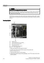
Removing a thyristor
①
M8 fixing screw
②
2 x M12 fixing screws (on the underside)
③
M20 nuts for the clamping device
④
Groove of the guide bolt
⑤
A5E00291256 open-ended wrench
Figure 9-8
Thyristor replacement
1. Detach the gate lead from the thyristor electronics.
2. Insert the open-ended wrench
⑤
into the groove of the guide bolt
④
.
3. Remove the fixing screw
①
.
4. Loosen the fixing screws
②
on the underside.
5. Loosen the two nuts
③
evenly, working alternately on each. This releases the heat sink/
thyristor assembly.
Maintenance
9.7 Repairs
SINAMICS GL150 6SL38502UM114PA0Z
124
Operating Instructions Rev.201910281441 EXAMPLE


