8 – 22
3ZW1012-0WL11-0AB1
8.1.9
Schutzfunktionen
8.1.9.1 Grundschutzfunktionen
Die Grundschutzfunktionen des Überstromauslösers sind ohne
zusätzliche Hilfsspannung sichergestellt. Die erforderliche Energie
wird von schalterinternen Energiewandlern bereitgestellt.
Für die Bewertung der Ströme wird durch die Elektronik des Über-
stromauslösers der Effektivwert (r.m.s.) berechnet.
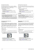
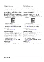
Die Parametrierung der einzelnen Funktionen erfolgt typenabhän-
gig mittels:
- Drehkodierschalter (ETU15B … 45B)
- elektronischer Datenübertragung (ETU76B) über:
- TD400 und die Software "powerconfig"
- die COM-Module mit einem PC mit installierter Software
„powerconfig“
→
- Bedientastenfeld (ETU76B).
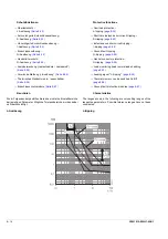
Überlastschutz – L-Auslösung
Der Einstellwert I
R
bestimmt den maximalen Dauerstrom, bei dem
der Schalter ohne Auslösung betrieben werden kann. Der Träg-
heitsgrad t
R
bestimmt, wie lange eine Überlast andauern kann,
ohne dass es zu einer Auslösung kommt.
Die Auslösekennlinie hat eine I
2
t-Charakteristik. Für einige Über-
stromauslöser besteht die Möglichkeit, auf eine I
4
t-Charakteristik
umzuschalten.
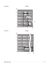
Kurzverzögerte Kurzschlussauslösung –
S-Auslösung
Bei den Überstromauslösern ETU25B, ..27B, ..45B und ..76B kann
die Auslösung infolge eines Kurzschlussstromes I
sd
um die Zeit t
sd
verzögert werden.
Damit kann eine Selektivität des Kurzschlussschutzes in Schaltan-
lagen mit mehreren Staffelebenen erreicht werden.
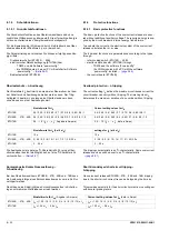
Einstellwerte für I
R
Current setting values for I
R
ETU15B
0,5 / 0,55 / 0,6 / 0,65 / 0,7 / 0,75 / 0,8 / 0,85 / 0,9 / 1
0.5 / 0.55 / 0.6 / 0.65 / 0.7 / 0.75 / 0.8 / 0.85 / 0.9 / 1
ETU25B, …27B, ..45B
0,4 / 0,45 / 0,5 / 0,55 / 0,6 / 0,65 / 0,7 / 0,8 / 0,9 / 1,0
0.4 / 0.45 / 0.5 / 0.55 / 0.6 / 0.65 / 0.7 / 0.8 / 0.9 / 1.0
ETU76B
0,4 ... 1,0 (I
R
= … x I
n
, Angabe in Ampere)
0.4 ... 1.0 (I
R
= … x I
n
, data in Amps)
Einstellwerte für t
R
(bei 6 x I
R
)
settings for t
R
(at 6 x I
R
)
ETU15B
10 s
10 s
ETU25B, …27B, ..45B
2 / 3,5 / 5,5 / 8 / 10 / 14 / 17 / 21 / 25 / 30 s
2 / 3.5 / 5.5 / 8 / 10 / 14 / 17 / 21 / 25 / 30 s
ETU76B
2 … 30 s
2 … 30 s
Einstellwerte für I
sd
(Angabe in Ampere)
Current setting values for I
sd
(data in Amps)
ETU25B, …27B, ..45B
I
sd
= (1,25 / 1,5 / 2 / 2,5 / 3 / 4 / 6 / 8 / 10 / 12) x I
n
I
sd
= (1.25 / 1.5 / 2 / 2.5 / 3 / 4 / 6 / 8 / 10 / 12) x I
n
ETU76B
I
sd
= 1,25 x I
n
…
0,8 x I
cw
I
sd
= 1.25 x I
n
…
0.8 x I
cw
8.1.9
Protective functions
8.1.9.1 Basic protective functions
The basic protective functions of the overcurrent release are ensu-
red without additional auxiliary voltage. The required energy is sup-
plied by the circuit breaker's internal energy transformers.
To evaluate the currents, the electronic system of the overcurrent
release calculates the r.m.s value.
The individual functions are parameterised according to the types
through:
- rotary coding switch (ETU15B … 45B)
- electronic data transfer (ETU76B) through
- TD400 and the software "powerconfig"
- the COM modules with a PC with the software
“powerconfig” installed
→
- the control board (ETU76B)
Overload protection – L-tripping
The current setting I
R
defines the maximum continuous current the
circuit breaker can carry without tripping. The time-lag class t
R
determines the maximum duration of an overload without tripping.
The tripping characteristic is an I
2
t-characteristic. Some overcurrent
releases can be switched over to an I
4
t-characteristic.
→
Short-time-delayed short-circuit tripping –
S-tripping
On overcurrent releases ETU25B, ..27B, ..45B and .76B, tripping
due to the short-circuit current I
sd
can be delayed by the time t
sd
.
This provides selectivity for the short-circuit protection in switchgear
with several grading levels.
Summary of Contents for 3ZW1012-0WL11-0AB1
Page 15: ...3ZW1012 0WL11 0AB1 0 XV ...
Page 87: ...3ZW1012 0WL11 0AB1 8 15 S Auslösung I Auslösung S tripping I tripping ...
Page 88: ...8 16 3ZW1012 0WL11 0AB1 Erdschlussauslösung Ground fault tripping ...
Page 359: ...3ZW1012 0WL11 0AB1 27 5 ...
Page 360: ...27 6 3ZW1012 0WL11 0AB1 ...
Page 366: ......
Page 367: ......

