3ZW1012-0WL11-0AB1
5 – 5
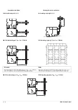
5.2.3
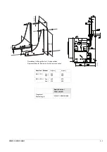
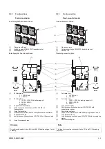
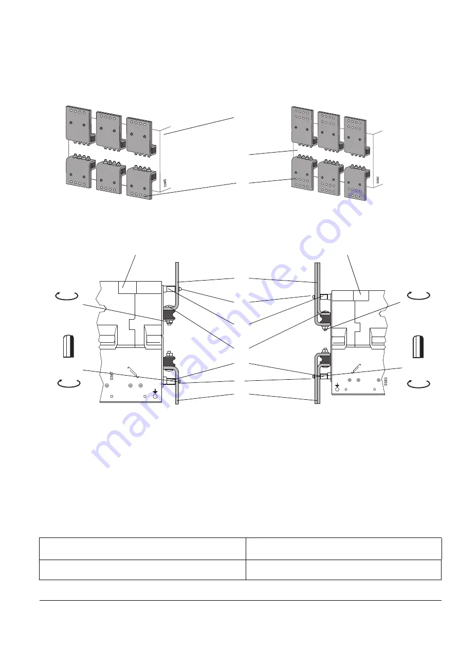
Front connection
Fixed-mounted breaker
Two variations are offered:
(1)
Standard version
(2)
Version according to DIN 43673 (double hole row)
(3)
Holes Ø 13.5
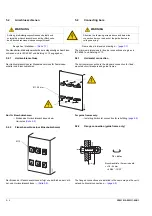
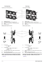
Fastening connecting bars:
(1)
For frame size:
I
≤
1000 A and
II
≤
2000 A
(2)
For frame size:
I
1250 A - 2000 A, breaking capacity H
II
2500 A, 3200 A
III 4000 A
(3)
Long connecting bar
(4)
Short hexagon socket-head screw ISO 4762 M6 with
conical spring washer
(5)
Short distance sleeve
(6)
Coach screw DIN 603 M12 with conical spring washer and nut
(7)
Long distance sleeve
(8)
Long hexagon socket-head screw ISO 4762 M6 with conical spring
washer
(9)
Short connecting bar
5.2.3
Frontanschluss
Festeinbauschalter
Ausführung der Anschlussschienen:
(1)
Standardausführung
(2)
Ausführung nach DIN 43673 (Doppellochreihe)
(3)
Bohrungen Ø 13,5
Befestigung der Anschlussschienen:
(1)
Für Baugröße:
I
≤
1000 A und
II
≤
2000 A
(2)
Für Baugröße:
I
1250 A - 2000 A, Schaltvermögen H
II
2500 A, 3200 A
III 4000 A
(3)
Lange Anschlussschiene
(4)
Kurze Innensechskantschraube ISO 4762 M6 mit
Spannscheibe
(5)
Kurze Distanzhülse
(6)
Schlossschraube DIN 603 M12 mit Spannscheibe und Mutter
(7)
Lange Distanzhülse
(8)
Lange Innensechskantschraube ISO 4762 M6 mit Spannscheibe
(9)
Kurze Anschlussschiene
Hinweis
Note
Diese Anschlussart ist in der BG II und BG III Schaltvermögen C nicht
zulässig.
This type of connection is not permitted in FS II and FS III breaking
capacity C.
(1)
(2)
(3)
85 Nm
8 Nm
85 Nm
(1)
(2)
(4)
(5)
(6)
(7)
(8)
Gr. / Size
5
8 Nm
Gr. / Size
5
(9)
(3)
Summary of Contents for 3ZW1012-0WL11-0AB1
Page 15: ...3ZW1012 0WL11 0AB1 0 XV ...
Page 87: ...3ZW1012 0WL11 0AB1 8 15 S Auslösung I Auslösung S tripping I tripping ...
Page 88: ...8 16 3ZW1012 0WL11 0AB1 Erdschlussauslösung Ground fault tripping ...
Page 359: ...3ZW1012 0WL11 0AB1 27 5 ...
Page 360: ...27 6 3ZW1012 0WL11 0AB1 ...
Page 366: ......
Page 367: ......


