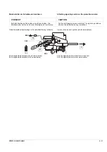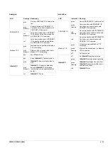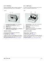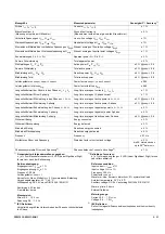
8 – 86
3ZW1012-0WL11-0AB1
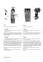
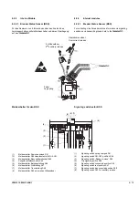
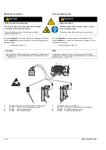
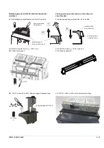
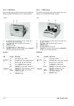
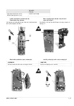
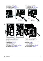
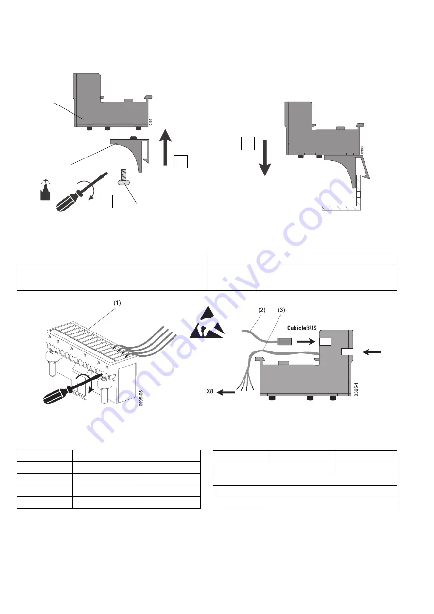
COM-Modul am Festeinbauschalter montieren
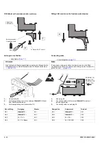
Leitungen anschließen
→
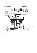
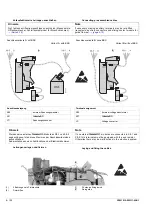
Schaltpläne
(1)
Handstecker X8
(2)
Verbindungsleitung zum ersten externen
c
-Modul
oder Abschlusswiderstand
(3)
Verbindungsleitung zum Handstecker X8
Hinweis
Note
Ggf. fehlende Hilfsstromanschlüsse nachrüsten (Messerleiste,
Hilfsstromstecker, Schleifkontaktmodul für Einschubrahmen).
→
If necessary missing auxiliary terminals may be retrofitted
(receptacle, auxiliary connectors and sliding contact module for
guide frames).
→
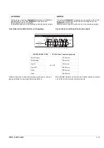
Beschriftung
Belegung
Klemme
X8-1
c
–
X8.1
X8-2
c
+
X8.2
X8-3
24 V DC +
X8.3
X8-4
24 V DC Masse
X8.4
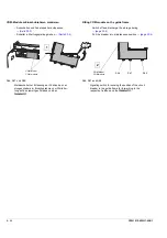
PZ 2
2
1
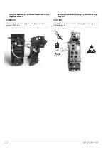
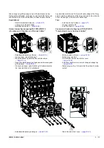
COM-Modul
COM module
Betätigungsmodul
Operating module
3 x Plastite RX-PT 8-16x12
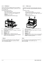
PROFINET IO
Modbus TCP
PROFIBUS DP
Modbus RTU
Fitting
COM
module on the fixed-mounted breaker
Connecting wires
→
Circuit diagrams
(1)
Hand plug X8
(2)
Connecting cable to first external
c
module or
terminating resistor
(3)
Connecting cable to hand plug X8
Designation
Assignment
Terminal
X8-1
c
–
X8.1
X8-2
c
+
X8.2
X8-3
24 V DC +
X8.3
X8-4
24 V DC GND
X8.4
3
Summary of Contents for 3ZW1012-0WL11-0AB1
Page 15: ...3ZW1012 0WL11 0AB1 0 XV ...
Page 87: ...3ZW1012 0WL11 0AB1 8 15 S Auslösung I Auslösung S tripping I tripping ...
Page 88: ...8 16 3ZW1012 0WL11 0AB1 Erdschlussauslösung Ground fault tripping ...
Page 359: ...3ZW1012 0WL11 0AB1 27 5 ...
Page 360: ...27 6 3ZW1012 0WL11 0AB1 ...
Page 366: ......
Page 367: ......


