5
ELECTRICAL INSTALLATION
42
8027439/V1-0/2022-02|SICK
A D D E N D U M T O O P E R A T I N G I N S T R U C T I O N S | Track and trace cabinet TTC100-2
Subject to change without notice
5.2.5
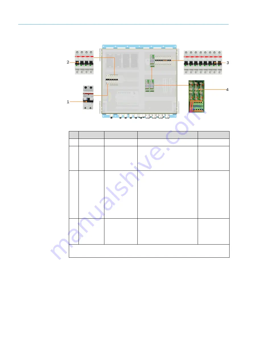
RCD and fuse module
Fig. 26: RCD and fuse module in the cabinet
No. Fuse
Fuse type
Protected circuit
Value/behavior
1
-FB1
RCD
-X110 Schuko plug socket
30 A/B6A
2
-FC20
-FC21
-FC22
-FC23
Circuit breakers
each 1-pin
AC 100...264 V supply voltage
for power supply modules -TB1,
-TB2,-TB3 and TB4
10 A /B10A
3
-FC121
-FC131
-FC122
-FC132
-FC123
-FC133
-FC124
-FC134
Circuit breakers
each 1-pin
24 V supply voltage to the
ICR cameras (protects the
terminals on the -XD120
terminal block)
10 A /B10A
4
-FC
x
.1 to -
FC
x
.6
x
= 1 to 3
Fine-wire fuse
24 V supply voltage to the
internal components and
external sensors (protects
terminals 11+ .. 26 +)
FC1 - FC5:
4 A/slow-blow*
FC6:
2 A/slow-blow*
* Standard assignment. May differ depending on the application (see electrical schematic of the
system)
Tab. 8: RCD and fuse modules in the cabinet


