8016903/ZP97/2017-07-27 • Subject to change without notice •
SICK AG
•
Waldkirch
•
Germany
•
www.sick.com
T i M 3 5 x / T i M 3 6 x | S i C K
3
SOPAS removes the marking rectangle and instead con-
nects the two nearest marking rectangles with a new line.
Rotating the field pair around the central axis along with
the TiM
>
In order to align the position of the field pair in SOPAS to
the conditions on site from the user's perspective, enter
and confirm the desired angle of rotation in the 0.0° input
field (negative sign "
–
" means turn right).
Setting up the reference contour field
In each field set, any field can be selected as a reference
contour field. The reference contour field is used to monitor
contours. This makes it possible to recognize when the
background is no longer detected in the required field – for
example, as a result of covering or rotating the sensor.
The TiM uses the same evaluation strategy for all reference
contour fields (evaluation time and blanking size).
1.
Select the required field in the field set.
2.
Select the
r
eFerenCe
Contour
Field
check mark under
F
ield
seleCtion
.
3.
Delete the two field positions closest to the sensor.
4.
Mark the two remaining field positions and shift them
outside of the required reference contour area.
5.
Use the
button to switch to the configuration for the
reference contour field start points. The field starting
points must lie between the scan line and the scanner so
that the scan line passes between the start and end points
of the reference contour field.
Contour as reference field
Field start point
TiM
Field end point
Scan line
6.
Depending on the required shape of the reference contour
field, create additional field points between the sensor and
the reference contour field. The distance between the start
and end points of the reference contour field should be
approximately 20 cm.
>
The
button can be used to switch between the start
and end points of the reference contour field for editing
purposes. The active points are highlighted in light green
while the deactivated points are dark green.
Some other useful functions
•
button: Display the fields in the polar coordinate
system
•
button: Change the view of the TiM/ fields from above
(TiM: black) to the view from below (TiM: blue)
•
or
button: Switch off the display the full measur
-
ing line or display a dotted measuring line.
Response time, blanking size and holding time
>
Adjust the response time of the fields, the blanking size
of objects, and the holding time of the OUT 1 and OUT 4
switching outputs under
s
ettinGs
on the right side of the
program window. All three values are valid for both fields
and switching outputs.
When selecting the response time, note that the TiM's
internal reaction time must also be added (max. 67 ms).
>
To test the effects of the changed settings, click on the
F
ield
evaluation
monitor
tab at the top.
If the changed fields have been transferred to the TiM as
described
,
SOPAS will also display these in the monitor,
displaying the infringed fields in yellow. If you wish to
observe another field set, it must first be activated accord
-
ingly using the switching inputs. If you wish to observe
another field set, it must first be activated accordingly
using the switching inputs.
The blanking size is the cross-section of the object after
which an object not previously in the viewing area of the TiM
leads to a field infringement.
Completing the configuration process
>
Permanently save the entire configuration:
Parameter set in: TiM click the
button
Configuration file on the PC: click the
button.
Default settings TiM
Parameter
Value
Blanking size
Cross-section 200 mm
Response time of the fields
335 ms (5 scans)
Holding time of the switching outputs
335 ms (5 scans)
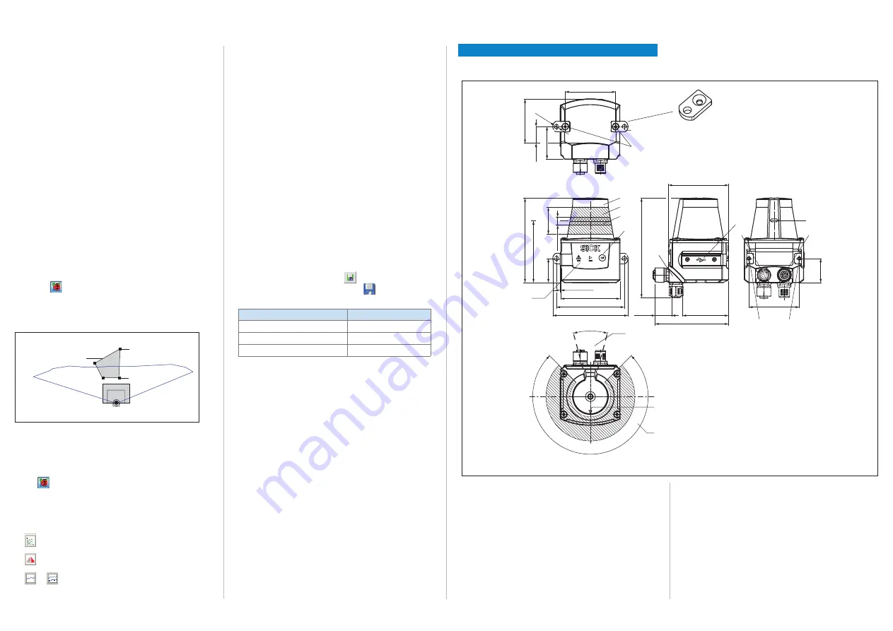
Description of the device
Device layout
4
5
3
ß
7
All dimensions in mm (inch)
9
à
2
2
225°
‒45°
180°
0°
ä
ã
85.75
(3.38)
27.
3
[24.
4
62.46
(2.46)
60
(2.30)
0.7
(0.03)
[68.8
(2.71)
]
[76.25
(3.00)
]
61
(2.40)
46.71
(1.84)
74.39
(2.93)
101.12
(3.98)
17.37
(0.68)
51
(2.01)
30°
90°
6
á
8
â
2
1
Mounting set 1
2 x
51
(2.01)
44.79
(1.76)
16.79
(0.66)
33
(1.3
)
[Ø 4
.3
(0.17
)
]
(0.96)
]
(1.07)
8
(0.31)
24.
4
(0.96)
1
2 x straight plates with M3 x 4 mm screw (included in scope of
delivery)
2
M3 threaded mounting hole, 2.8 mm deep (blind hole thread)
3
Optical hood
4
Receiving range (light inlet)
5
Transmission range (light emission)
6
Function button for teach-in
7
Red and green LED (status displays)
8
Swivel connector unit with electrical connections
and
á
9
Micro USB port, behind the black plastic cover
('Aux interface' connection for configuration with PC)
"Power/inputs and outputs" connection, 12-pin M12 male connector
à
Marking for the position of the light emission level
á
Ethernet connection, 4-pin M12 female connector
â
Area in which no reflective surfaces are allowed for mounted devices
ã
Bearing marking to support alignment (90° axis)
ä
270° aperture angle (visual range)


