background image

Antenna

Part no.

Polariza‐

tion

Carrier frequency

range 

5)

Gain (typ‐

ical)

H+S SPA-900/65/8/0/LCP_C

1)

6052510

LHCP 

3)

865 MHz ... 928

MHz

8 dBic

H+S SPA-900/25/9/0/LCP_C

1)

6052511

LHCP 

3)

865 MHz ... 928

MHz

9 dBic

H+S SPA-900/65/9/0/LCP_C

1)

6052897

LHCP 

3)

865 MHz ... 928

MHz

8 dBic

1)

This antenna is only available in conjunction with a SICK system solution (e.g., RFGS or
RFMS).

2)

RHCP = right-hand circular polarization.

3)

LHCP = left-hand circular polarization.

4)

LV = linear vertical polarization.

5)

To ensure proper operation, the carrier frequency range of the device must be 

within

 the

carrier frequency range of the connected external antennas.

14 Sources for obtaining more information

Additional information about the device, its optional accessories, and fieldbus

modules can be found in electronic format on the following product pages on the

Internet at:

14.1 RFID read/write device RFU630-131xx (UHF)

www.sick.com/RFU63x

Ordering information

Device and its regional radio variants

Compatible accessories, including transponders, cables, brackets, trigger

sensors, connection modules, fieldbus modules

Documentation

Online data sheet: summary of type-specific technical data including dimen‐

sional drawing for the selected device

Quickstart RFID read/write device RFU630-131xx (UHF)

RFID read/write device operating instructions RFU63x/RFU65x (UHF)

Technical information RFU parameters to support the configuration of the

device

Dimensional drawing and 3D CAD dimension models of the device in various

electronic formats

On request: Overview of the command strings of the device

Documentation of the fieldbus modules

Documentation of accessories (mounting systems, connection technology)

Certificates

EU declaration of conformity and further certificates

Software

SOPAS ET configuration software

SDD files (device description files for SOPAS ET)

Function blocks for communication between a programmable logic controller

(PLC) from different manufacturers and the device or the fieldbus modules.

Support is also available from your sales partner: 

www.sick.com

14.2 Copyright notices

Open source programs

SICK uses open-source software in the device. This software is licensed by the

rights holders using the following licenses among others: the free licenses GNU

General Public License (GPL Version2, GPL Version3) and GNU Lesser General

Public License (LGPL), the MIT license, zLib license, and the licenses derived from

the BSD license.
This program is provided for general use, but WITHOUT ANY WARRANTY OF ANY

KIND. This warranty disclaimer also extends to the implicit assurance of mar‐

ketability or suitability of the program for a particular purpose.
More details can be found in the GNU General Public License.
View the complete license texts here: 

www.sick.com/licensetexts

Printed copies of the license texts are also available on request.
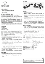
 

A

Cable 

9

Cable 

ß

Cable 

8

SOPAS ET

SOPAS ET

"Power/Serial Data/CAN/I/O"

(Aux 1, Host 1)

...

...

1 2

V

S

GND

PC

"Ethernet" (Aux 2)

External antennas


4

...

1

3

Ethernet

Ethernet

RFU630-

131xx

7

11 10 12

Trigger
sensor

SGND

Sens 1

V

S

1

Out

GND

V

S

2

3

Connection

module

Configuration
Reading result 
display
Transponder 
access
Reading 
diagnostics

Cable 

5

"USB" (Aux 3), 

for temporary use only 

6

USB

USB

1

Trigger sensor for read cycle

2

Supply voltage V

S

3

Connection module CDB650-204 or CDM420-0006

4

External antennas, e.g. RFA630-000 (region Europe and possibly other countries)

5

Adapter cable (male connector, USB, Micro-B type/male connector, USB, type A)

6

USB, alternative to Ethernet Aux port. The USB interface is only for temporary use as a service interface.

7

Configuration with SOPAS ET, prepared representation of the read result, transponder access or reading diagnostics

8

Adapter cable (male connector, M12, 4-pin, D-coded / male connector, RJ-45, 8-pin)

9

For CDB650-204: Connection cable 1:1 (female connector, M12, 17-pin, A-coded / male connector, M12, 17-pin, A-coded)
For CDM420-0006: Adapter cable (female connector, M12, 17-pin, A-coded / male connector, D-Sub-HD, 15-pin)

ß

Cable (e.g. male connector, TNC reverse/male connector, TNC reverse)

8016526/160H/2019-11-14/en

RFU630-131xx | SICK

9

Summary of Contents for RFU630-131 Series

Page 1: ...onment During operation with the integrated antenna and or the external RFA630 x01 antennas USA region and possibly other countries a safety distance of at least 30 cm must be maintained between the antenna and the human body Complete region assignment of the RFU630 131xx see Device overview page 8 Conditions for specified enclosure rating To ensure compliance with the IP67 enclosure rating of the...

Page 2: ...cessing the card Lights up Red The memory card is inserted However the device cannot read data on the memory card Possible causes The memory card does not contain any data The content is not readable The memory card is defective Lights up Orange 1 A function is started with SOPAS ET which requires a memory card for writing However the memory card is not connected 1 Prerequisite In SOPAS ET the SD ...

Page 3: ...e permissible ambient conditions for operating the device must be observed e g assigned radio region ambient temperature see Technical data page 6 and ground potential see Electrical installation page 4 The device must be mounted using all 4 M6 or 3 M5 blind tapped holes pro vided see Device view page 2 If necessary stable mounting equipment with sufficient load bearing capac ity and appropriate d...

Page 4: ... same at all grounding points Where local conditions do not meet the requirements for a safe earthing method take appropriate measures e g ensuring low impedance and current carrying equipotential bonding NOTE For recommended measures for eliminating hazards see the Electrical installation chapter in the RFU63x 65x RFID read write device UHF operat ing instructions in the Internet at www sick com ...

Page 5: ...e RFU630 under the devices avail able depending on the connected communication interface e g in the Ether net default Ethernet address IP address 192 168 0 1 subnet mask 255 255 255 0 SOPAS ET establishes communication with the device and loads the associated device description file The Quickstart tab opens 6 2 Detecting a transponder in Quickstart mode 1 Bring one or more standards compliant UHF ...

Page 6: ... and caps completely screwed on Do not store outdoors To ensure that any residual moisture present can escape do not store the device in airtight containers Do not expose to any aggressive substances Storage conditions dry dust free no direct or indirect sunlight as little vibration as possible Storage temperature and relative humidity see Technical data page 6 9 Repairs Repair work on the device ...

Page 7: ...eb server fieldbus controller PLC with additional support by SICK function blocks Programming Application specific programming with SICK AppStudio 12 devel opment environment You can find further information on the Internet at www sick com SICK_AppStudio 1 Service for example configuration diagnosis transponder access or display of the read result 2 Function blocks for PLC types from different man...

Page 8: ...y energy and if not installed and used in accordance with the instruction manual may cause harmful interference to radio communications Operation of this equipment in a residential area is likely to cause harmful interference in which case the user will be required to correct the interference at his own expense 4 To comply with FCC part 15 rules in the United States the system must be pro fessiona...

Page 9: ...s and the device or the fieldbus modules Support is also available from your sales partner www sick com 14 2 Copyright notices Open source programs SICK uses open source software in the device This software is licensed by the rights holders using the following licenses among others the free licenses GNU General Public License GPL Version2 GPL Version3 and GNU Lesser General Public License LGPL the...

Page 10: ...ennas e g RFA630 000 region Europe and possibly other countries 8 Null modem cable female connector D Sub 9 pin female connector D Sub 9 pin crossed TxD and RxD 9 Serial RS 232 alternative to USB or Ethernet Aux port ß USB alternative to serial RS 232 or Ethernet Aux port The USB interface is only for temporary use as a service interface à Adapter cable male connector USB Micro B type male connect...

Reviews: