Chapter
5
MSC800
8011540/14B8/2019-06-06
Operating instructions | SICK
65
Subject to change without notice
Electrical installation
Connect data interfaces to the host/PC in an EMC-compliant manner with shielded
cable. Observe the maximum length of cable when doing so.
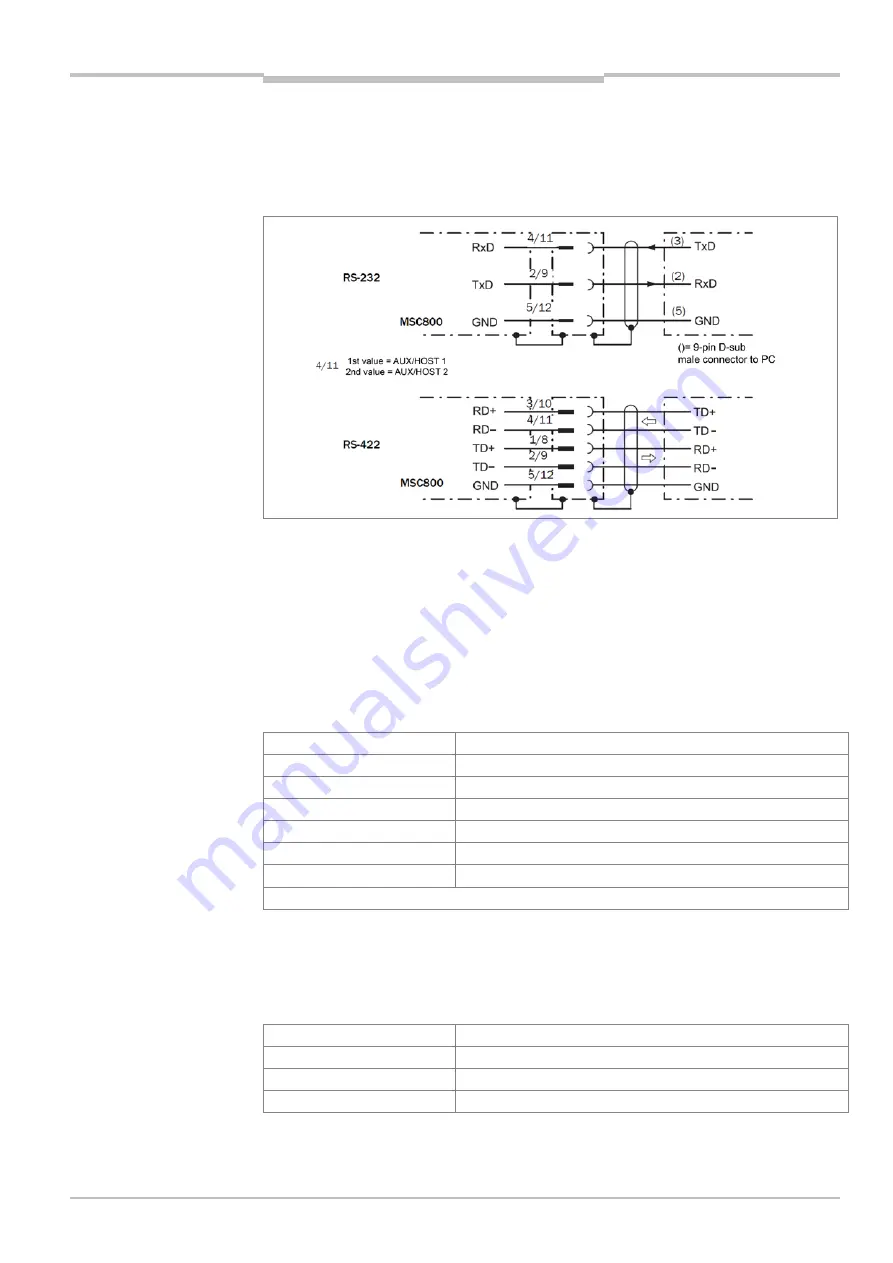
Wire the RS-232 or RS-422 versions as shown in the following figure. AUX 1 (RS-232)
can also alternatively be wired via the 9-pin D-Sub male connector AUX 1.
Fig. 24: Wiring of the HOST data interfaces (terminal block X3)/AUX (terminal block X9)
5.4.9
CAN 1/CAN 2 data interface of the logic unit
Framework conditions for the CAN Interface
The SICK-specific CAN-SENSOR network is based on the CAN bus. It is set up in line
topology.
The following table shows the maximum permitted length of the CAN bus for the CAN
SENSOR network depending on the data transmission rate selected.
Data transmission rate
Maximum data cable length
20 kBit/s
2,476 m
50 kBit/s
976 m
100 kBit/s
576 m
125 kBit/s
476 m
250 kBit/s
226 m
500 kBit/s
1)
76 m
1) Default in the MSC800.
Tab. 39 CAN bus: maximum lengths of cable depending on the data transmission rate
The following table shows the maximum permitted total length of all stub cables depending
on the data transmission rate. This total length must not be exceeded. Each individual
stub cable may be a maximum of 6 m long.
Data transmission rate
Maximum total of all stub cables
125 kBit/s
156 m
250 kBit/s
78 m
500 kBit/s
39 m
Tab. 40 CAN bus: maximum lengths of stub cables depending on the data transmission rate


