


Table 2: Field types and their function
Safe switch off (according
to ISO 13849-1)
Yes (PL d)
Yes (PL d)
Yes (PL d)
Max. scanning range of
the safety laser scanner
Variant-dependent:
4.0 m
5.5 m
9.0 m
Variant-dependent:
4.0 m
5.5 m
9.0 m
Variant-dependent:
4.0 m
5.5 m
9.0 m
Purpose
Detection and pro‐
tection of people
Tamper protection
e.g. door monitoring
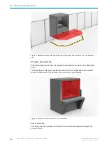
The protective field protects the hazardous area of a machine or vehicle. As soon as the
electro-sensitive protective device detects an object in the protective field, it switches
the associated safety outputs to the OFF state. This signal can be passed to controllers
resulting in the dangerous state coming to an end, e.g. to stop the machine or the
vehicle.
Figure 5: Protective field, shown in red in this document
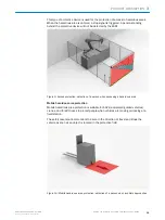
The contour as reference field monitors a contour of the environment. The safety laser
scanner switches all safety outputs to the OFF state if a contour does not match the set
parameters, because, for example, the mounting of the safety laser scanner has been
changed.
National and international standards require or recommend that a reference contour is
monitored, if the safety laser scanner is used in vertical operation for hazardous point
protection or for access protection.
The reference contour field detects unintentional and intentional changes to the posi‐
tion or alignment of the safety laser scanner. Unintentional changes may be caused by
vibrations for example. An example of an intentional change is deliberate tampering to
disable the functionality of the safety laser scanner.
3
PRODUCT DESCRIPTION
16
O P E R A T I N G I N S T R U C T I O N S | microScan3 Core I/O AIDA
8017784/1ELL/2022-01-21 | SICK
Subject to change without notice