


6.3
Connections and pin assignment
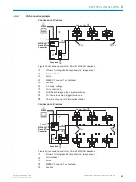
Overview
P2
P1
P3
X2
X1
1
2
3
4
5
1
P1: GB Ethernet 1
2
P2: GB Ethernet 2
3
P3: GB Ethernet 3
4
X2: Power/CAN
5
X1: Power/CAN/serial interface/IO
Power/CAN/serial interface/IO
3
1
7
2
6
5
4
8
13
14
17
15
9
10
12
16
11
Figure 10: Male connector, M12, 17-pin, A-coded
The serial interface and the digital inputs and outputs are not available. Do not connect
the associated pins.
PIN
Power/IO
Information
1
GND
2
V
S
3
CAN L
4
CAN H
5
TD+ (RS-422), Host
Do not connect.
6
TD- (RS-422), Host
TxD (RS-232), host
Do not connect.
7
TxD (RS-232), Aux
Do not connect.
8
RxD (RS-232), Aux
Do not connect.
9
SensGND
Do not connect.
10
Sensor 1, digital input
Do not connect.
11
RD+ (RS-422) Host
Do not connect.
12
RD- (RS-422), host
RxD (RS-232), host
Do not connect.
13
Result 1, digital output
Do not connect.
14
Result 2, digital output
Do not connect.
15
Sensor 2, digital input
Do not connect.
16
Result 3, digital output
Do not connect.
17
Result 4, digital output
Do not connect.
6
ELECTRICAL INSTALLATION
30
O P E R A T I N G I N S T R U C T I O N S | Lector85x Flex
8027859//2022-06-22 | SICK
Subject to change without notice