5
ELECTRICAL INSTALLATION
48
8011325/18IM/2020-07-02|SICK
O P E R A T I N G I N S T R U C T I O N S | ICR880/890
Subject to change without notice
5.1.2
Connecting several camera systems to a controller unit
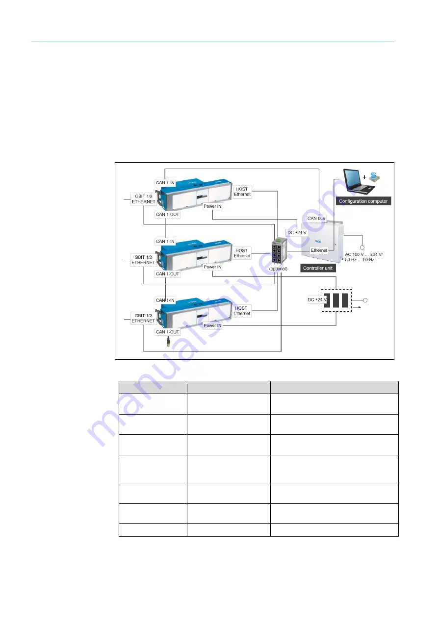
Several camera systems can be connected to the controller unit via CAN bus.
For configuration, the camera systems are usually connected to an Ethernet switch via
the HOST ETHERNET interface. The configuration PC with the SOPAS-ET configuration
software then accesses the camera systems temporarily via Ethernet.
The Gbit interfaces of the camera systems can be connected to the Ethernet switch
for rapid image transmission.
The power required for the camera systems is provided by additional power supply
modules.
Fig. 35: Connection principle of several camera systems (multi-side reading)
Connection (camera) Function
Connect to
POWER OUT
Voltage supply of the
illumination unit
POWER IN connection of the illumination
unit
ILLUMINATION
Control of the illumination
unit
ILLUMINATION connection of the
illumination unit
POWER IN
DC 24 V voltage supply
Connection to internal power supply unit of
the controller unit
CAN 1-IN
Internal CAN sensor
network
Connection to CAN bus of the controller
unit or to CAN-OUT of the next camera
system
CAN 1-OUT
Internal CAN sensor
network
Connection to CAN 1-IN of the next camera
system or termination resistor
HOST Ethernet
Data interface for
configuration
Connection to Ethernet interface of the
controller unit via Ethernet switch
GBIT 1/2 ETHERNET
Image transmission
Server for image representation (optional)
Tab. 11: Connection principle of several camera systems (multi-side reading)


