PRODUCT DESCRIPTION
3
31
8011325/18IM/2020-07-02|SICK
Subject to change without notice
O P E R A T I N G I N S T R U C T I O N S | ICR880/890
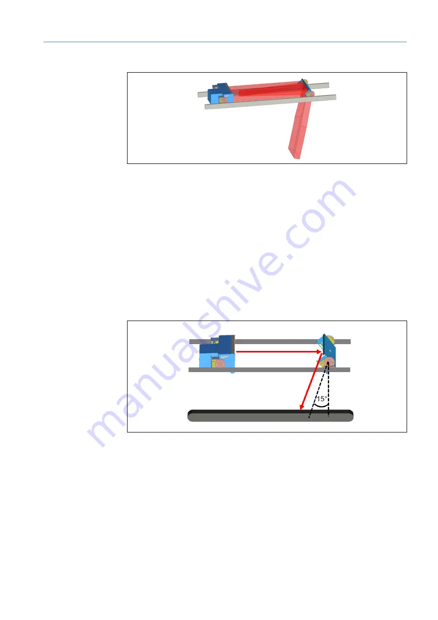
If a deflector mirror is used, the light is deflected onto the reading field.
Fig. 13: Deflector mirror principle of operation
The illumination unit is controlled by the camera and can be switched on continuously or
for the duration of the internal reading gate.
If, due to an error, the reading gate is not ending (e.g., the conveyor system stops), the
illumination unit automatically switches off after the adjustable time-out (switch-off delay).
To avoid confusion, the illumination unit must be switched on for at least three seconds.
3.4.5
Position and alignment
Depending on the arrangement of the camera system on the mounting frame, the position
and inclination angle of the camera and deflector mirror must be set.
To avoid total internal reflection, the emitted light must not hit directly perpendicular to
the bar code, but rather tilted at an angle of approx. 15° (β = Skew) relative to vertical.
This prevents the interference of surface reflections (total internal reflection).
Fig. 14: Inclination angle of the camera system
3.4.6
Increment configuration
To control the time frequency of the camera, the camera system needs information about
the conveyor speed. An external incremental encoder provides pulses, from which the
current conveyor speed is determined.
The conveyor speed is derived from the number of pulses and the resolution of the
external incremental encoder.


