


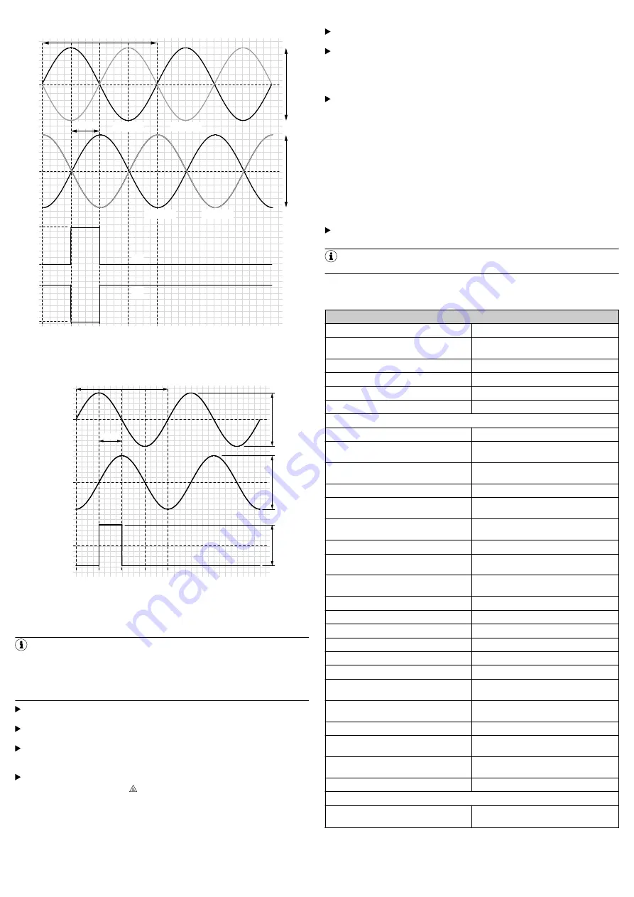
2,5 V
2,5 V
2,9 V
1,75 V
2,9 V
1,75 V
0,5 V
0,5 V
360° el.
90° el.
¯Z
COS+
COS–
SIN+
SIN–
Z
Figure 11: Encoder signals before subtraction at 120 Ω load, signal diagram dur‐
ing clockwise shaft rotation, as viewed in the direction of the shaft
COS+ – COS–
SIN+ – SIN–
Z – ¯Z
0 V
0 V
0 V
1 V
1 V
2,3 V
360° el.
90°el.
Figure 12: Encoder signals after subtraction at 120 Ω load, signal diagram during
clockwise shaft rotation, as viewed in the direction of the shaft
7
Commissioning
NOTE
Do not commission without a thorough check by qualified safety personnel!
Before you commission a system or a machine into which the DFS60S Pro is
integrated for the first time, the machine or system must be checked and
approved by qualified safety personnel. Observe the notes provided in
Observe the initialization time after switching on. The encoder does not out‐
put any valid signals during this time.
Check whether all the safety functions work as planned at all the relevant
speeds.
Check whether the maximum temperature that arises at the encoder’s oper‐
ating point while the encoder is being operated (see
,
“A”) is within the operating temperature range specified in the technical data.
If the temperature at the operating point is above 70 °C:
–
Attach the pictogram “Warning! Hot surfaces” in accordance with
IEC 60 4175041 in a visible location on the encoder housing.
–
Explain the meaning of the pictogram in the operating instructions of
the machine into which the encoder is being integrated.
7.1 Inspection
Further inspection measures are not required during operation.
8
Servicing
The DFS60S Pro is maintenance-free. Repairs cannot be carried out in the
event of a defect. Please contact us if you have any complaints.
Observe the mission time. The DFS60S Pro safe encoder has a maximum
mission time after which it must always be taken out of service. The bearing
service life must be taken into account in addition to the mission time T
M
.
The parameter which is first reached depending on the application deter‐
mines the time when the system must be taken out of operation.
The encoder’s year of manufacture is specified on the device label or pack‐
aging label as a four-digit code (yyww). The first two digits (yy) represent the
year (without the century), and the last two digits (ww) represent the calen‐
dar week of the manufacturing process.
9
Decommissioning
9.1 Protecting the environment
The safety encoder is designed to minimize its impact on the environment. It uses
a minimum of energy and resources.
b
Always act in an environmentally responsible manner at work. For this rea‐
son, please note the following information on disposal.
9.2 Disposal
Always dispose of unusable or irreparable devices in accordance with the
applicable waste disposal regulations specific to your country.
NOTE
We will be glad to help you dispose of these devices. Please contact us.
10 Technical data
DFS60S Pro data sheet
Performance
Number of sine/cosine periods per revolution
1,024
Measuring increment (not safety-related)
0.3 angular seconds
At 12-bit interpolation
Integral non-linearity
Typ. ± 45 angular seconds
19
Differential non-linearity
± 7 angular seconds
Reference signal, number
1
Reference signal, position
90°, electric, logically gated with sine/cosine
Mechanical data
Weight
Face mount flange
Servo flange
Approx. 0.30 kg
20
Through hollow shaft
Blind hollow shaft
Approx. 0.25 kg
21
Start up torque at 20 °C
Face mount flange
Servo flange
≤ 0.5 Ncm
Through hollow shaft
Blind hollow shaft
≤ 0.8 Ncm
Operating torque at 20 °C
Face mount flange
Servo flange
≤ 0.3 Ncm
Through hollow shaft
Blind hollow shaft
≤ 0.6 Ncm
Max. angular acceleration
≤ 5 × 10
5
rad/s²
Permissible shaft load (radial/axial)
80 N / 40 N
Permissible shaft movement (hollow shaft)
–
Static (radial/axial)
± 0.3 mm / ± 0.5 mm
Dynamic (radial/axial)
± 0.05 mm / ± 0.1 mm
Max. operating speed
21
Face mount flange
Servo flange
9,000 rpm
Through hollow shaft
Blind hollow shaft
6,000 rpm
Rotor moment of inertia
Face mount flange
Servo flange
8 gcm²
Through hollow shaft
Blind hollow shaft
56 gcm²
Bearing service life
22
3.6 × 10
9
revolutions
23
Electrical data
Electrical Interfaces
4.5 V … 32 V, sin/cos
1.0 V
SS
(differential)
19
Relates to unstressed stator coupling.
20
Relates to encoder with connector outlet.
21
The operating temperature must be measured at the rated speed and must be lowered by
3.0 K for each 1,000 rpm.
22
The mission time can also be limited by the bearing service life specific to the application.
23
Calculated for max. speed and temperature.
8016866/12N8/2019-01-31/de, en, es, fr, it
DFS60S Pro | SICK
13


