Chapter
12
Operating Instructions
C4000 Select
74
© SICK AG • Industrial Safety Systems • Germany • All rights reserved
8012247/RI61/2007-11-30
Ordering information
12.9
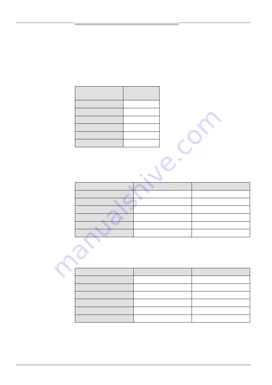
Additional front screen (weld spark guard)
Two additional front screens (weld spark guards) supplied for each part number.
The additional front screen fits both on the sender and on the receiver.
The additional front screen may be used only if the curved enclosure side is accessible.
An additional front screen reduces the scanning range of the system by 8 %. If sender
and receiver each use an additional front screen, the scanning range will be reduced by
16 %.
Protective field height
[mm]
Part number
300
2033235
600
2033237
900
2033239
1200
2033241
1500
2033243
1800
2033245
12.10
Deflector mirror
12.10.1
Deflector mirror PNS75 for protective field width 0…12 m (total)
Protective field height [mm]
Type number
Part number
300
PNS75-034
1019414
600
PNS75-064
1019416
900
PNS75-094
1019418
1200
PNS75-124
1019420
1500
PNS75-154
1019422
1800
PNS75-184
1019424
Dimensional drawing see Fig. 39 on page 68. Effect on the scanning range see Tab. 13 on
page 26.
12.10.2
Deflector mirror PNS125 for protective field width 4…18.5 m (total)
Protective field height [mm]
Type number
Part number
300
PNS125-034
1019425
600
PNS125-064
1019427
900
PNS125-094
1019429
1200
PNS125-124
1019431
1500
PNS125-154
1019433
1800
PNS125-184
1019435
Dimensional drawing see Fig. 40 on page 69. Effect on the scanning range see Tab. 13 on
page 26.
Notes
Tab. 51: Part numbers addi-
tional front screen (weld
spark guard)
Tab. 52: Part numbers
deflector mirror PNS75
Tab. 53: Part numbers
deflector mirror PNS125


