To boot from a camera configuration:
1.
Select
Camera configurations
from the menu.
2.
In the
Use on startup
column, select the
Camera configuration
that you want the device
to boot from.
✓
Next time the device boots, it will use the parameter values in the selected
configuration.
To load a camera configuration to the camera:
1.
Select
Camera configurations
from the menu.
2.
Select a configuration.
3.
Click
Load
.
✓
The configuration stored in the selected
Camera configuration
is now used on the
device.
9.2.3
Visualizing 2D data
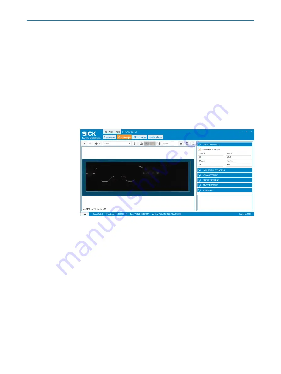
The control bar in the
2D Image
window contains visualization options for the acquired
2D image data. The control bar is located above the image viewer in the GUI.
Figure 72: Visualization options for the
2D Image
tab. The black region is the active extraction
region. The red line represents the extracted laser line. The orange line represents the extension
of the guaranteed field of view.
Show extraction region
Select the
Show area in 2D-image
checkbox to visualize the selected extraction region.
When the checkbox is selected, a blue overlay appears in the 2D image. The overlay
represents the parts of the image to be excluded from the generation of 3D image data.
The remaining dark area is the extraction area.
Simulate laser line extraction
Select the
Peak visualization
button to visualize an approximation of the extracted laser
line. The visualization shows where the laser line is detected in the selected extraction
region. This visualization aid is useful for tuning laser line extraction parameters such
as the
Exposure time
,
Multi slope mode (HDR)
,
Detection threshold
,
Search direction
and
Search
mode 3D
.
Simulate guaranteed field of view
Select the
Guaranteed FOV
button to visualize the guaranteed field of view for the device.
The orange line shows the region guaranteed to be covered by the device.
OPERATION
9
8026049//2021-04 | SICK
O P E R A T I N G I N S T R U C T I O N S | Ruler3000
73
Subject to change without notice


