background image

GETTING STARTED…


77 

8024172/V3-0/2021-01 
Subject to change without prior notice. 

                                                                                                                                       Operating instructions | LABEL CHECKER P6XX 


4.8.9


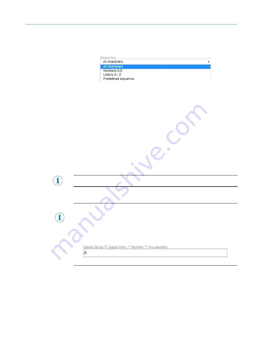
Character type 


Figure 43      Character  types 


All Characters – All characters and punctuation are read 
(ABCDEFGHIJKLMNOPQRSTUVWXYZ1234567890). 


Only numbers – Strictly numbers and punctuation are read (1234567890). 


Only letters A-Z - Only letters and punctuation are read 
(ABCDEFGHIJKLMNOPQRSTUVWXYZ). 


Predefined sequence - Text input of specify string. 

o


Specific string 


A few font packages such as Pharma or customized fonts do not support Character type 
selection. 


When the predefined sequence is enabled, the specific string sample must be arranged 
according to following rule: 

A = Capital letter 

* = Any character 

1 = Number 


Summary of Contents for 1086947

Page 1: ... OPE RAT I NG I NST RUCT IO NS LABEL CHECKER LBC6XX All in one solution for OCR and various labels checking task ...

Page 2: ...facturingLocation SICKAG Gisela SICK Str 1 79276Reute Deutschland Trademarks Windows is a registered trademarkMicrosoft Corporation Halcon is a registered trademark of MVTecSoftware Gmbh Original Documents The english issue 8024172 of this document is anoriginal document of the SICKAG SICKAG does not accept responsibilityforthe correctness of anyunauthorized translations of this document If in dou...

Page 3: ... Module components examples 14 3 3 2 Mounting and reflection prevention 19 3 4 Electrical installation 20 3 4 1 LBC621 connections pin assignment 20 3 4 2 LBC63x connections pin assignment 22 3 4 3 LBCP64x 65x connections pin assignment 24 4 Getting started 26 4 1 User interface at a glance 26 4 2 Login 28 4 3 Status results 30 4 4 Inspection result 31 4 5 Run tab 32 4 5 1 Create new job 33 4 5 2 ...

Page 4: ...to create the Object locator 65 4 7 7 Mask region 69 4 7 8 How to remove a region in the Object locator 70 4 8 OCR OCV tab 71 4 8 1 Add OCR OCV region 72 4 8 2 Region shape 72 4 8 3 Print type 72 4 8 4 Thresholdingmethod 73 4 8 5 Maximum mismatch 74 4 8 6 Specify number of characters 74 4 8 7 CRC Cyclic Redundancy Check 75 4 8 8 Font 75 4 8 9 Character type 77 4 8 10 Minimum confidence 78 4 8 11 R...

Page 5: ...ttings 134 4 12 2 How to save results 136 4 12 3 Draw results to image 136 4 12 4 Save results to file csv file 136 4 12 5 IP address 137 4 12 6 Port 137 4 12 7 Username 137 4 12 8 Password 137 4 13 Digital Inputs Outputs 138 4 13 1 Apply 138 4 13 2 Start inspection trigger settings 139 4 13 3 Output settings 140 4 13 4 Light settings 143 4 13 5 How to set up the Input Output settings 144 4 13 6 D...

Page 6: ...procedure and handling license file 200 5 3 Backup transfer to another camera and to HDD 208 5 4 Backup transferbetweendifferent versions of Software and Firmware different camera types 211 6 Troubleshooting 215 6 1 Overview of possible faults error 215 6 2 Detailed fault analysis 215 6 3 Resetting to factory mode 216 6 4 Beep description 216 6 5 Ready LED status description 217 6 6 Returning devi...

Page 7: ...nstructions LABEL CHECKER P6XX 7 6 Trigger and external illumination connection 232 7 7 Encoder connection directly or via CDB650 232 7 8 LBC621 accessories 233 7 9 Illumination color influence 234 7 10 Technical data 235 7 11 Additional accessories 238 7 12 Ordering information 238 ...

Page 8: ...l times Should the device be passed onto a third party these operatinginstructions should be handed over with it These operatinginstructions do not provideinformationonoperatingthe machine in which the device is integrated For furtherinformation referto the operating instructions of the particularmachine 1 2 Scope These operatinginstructions serve to incorporatethe device into a customersystem Ins...

Page 9: ...juries if not prevented WARNING Indicates a potentiallydangerous situation which maylead to a fatalityorserious injuries if not prevented CAUTION Indicates a potentiallydangerous situation which maylead to minor slight injuries if not prevented NOTICE Indicates a potentiallyharmful situation which maylead to material damage if not prevented NOTE Highlights useful tips and recommendations as well a...

Page 10: ...nd diagrams EU declarationof conformityforthe product family Dimensional drawings and 3DCADdimensionmodels in various electronic for mats These operatinginstructions availablein English and German and in other languages if necessary Otherpublications related to the devicesdescribedhere Publications dealingwith accessories 1 5 Customer service If you require anytechnical information ourcustomerserv...

Page 11: ... found in the operating instructions forthe relevant devices Please referto Chapter1 2 Scope Hazard due to lackof effectivenessofthe protectivedevice If there is non compliance it is possible that the dangerous state of the machine maynot be stopped ornot stopped in a timelymanner Please read this document carefullyand make sure that youunderstand the content fullybefore workingwith the device Fol...

Page 12: ...n Forparameterization a personis considered competent whenhe she has the expertise and experience in the relevant field and is sufficientlyfamiliarwith the applicationof the protective device onthe machine that he shecanassessits work safety aspects Commissioning Forcommissioning a personis considered competent whenhe shehas the expertise and experience in the relevant field and is sufficientlyfam...

Page 13: ...ets connectingcables and SDcard are only supplied if ordered separately 3 2 System requirements Operator interface Supported Web Browsers Google Chrome 69 0 3497 92 Mozilla Firefox 62 0 2 32 bit and Internet Explorer11 0 969919129 orthe most recent version SOPASair uses new web technologies such as HTML5 so technical incompatibilities canbe expected whenusingolderbrowsers 3 3 Hardware The Label Ch...

Page 14: ...Please be informedthat the LBC62x will not support Profinet until 2021 The followingsetup displays a varietyof Label Checkerconnections LBC621 Figure 1 Label Checker 621 connections Description CSN CAN not supported Setting Serial Image display PLC Programmable Logic Controller Diagnostics Digital Outputs e gsignal lamps FTP server image storage Digital inputse g forencoders photoelectric sensors ...

Page 15: ...ating instructions LABEL CHECKER P6XX LabelChecker connectionexamples Figure 2 LBC6xx connected via module CDB650 204 Description Label Checkercamera voltage supply24V DC PC Ethernet cable M12 8 pin x coded Connectionmodule CDB650 204 PowerI O cable M 12 17 pin A coded Trigger sensor ...

Page 16: ...at ing ins t r uc t ions LABEL CHECKER P6XX Subject to change without prior notice Figure 3 LBC6xx using external illumination and trigger sensor Description Label Checkercamera Trigger sensor PC Ethernet cable M12 8 pin x coded External Illumination ...

Page 17: ...prior notice Operating instructions LABEL CHECKER P6XX Figure 4 LBC65x and LBC642 using external illumination Description Label Checkercamera PC C mount lens External illumination Lens protective hood Ethernet cable M12 8 pin x coded Mountingbrackets Connectingcable ...

Page 18: ...ICK Oper at ing ins t r uc t ions LABEL CHECKER P6XX Subject to change without prior notice Figure 5 LBC6xx connected via CDF600 module Description Label Checkercamera Ethernet cable M12 8 pin x coded PC Connectioncable 2m PROFINETCDF600 2200 ...

Page 19: ... of direct reflections Whencamera is tilted the image is slightlydistorted and mayresult in worse performance whencertain inspections are performed i e Object Locator Image rectificationcanbe used to correct the effect of perspectivedistortion pleasefind subsection 4 6 7 onhow to performpicture calibrationrectification Typical values are between10 and 20 Whenusinga polarizingfilter the recommended...

Page 20: ...ce sender 6 TD RS 422 485 host TxD RS 232 host Host interface sender 7 TxD RS 232 AUX AUX interface sender 8 RxD RS 232 AUX AUX interface receiver 9 SensGND Digital input ground 10 Sensor1 Digital input 1 11 RD RS 422 485 host Host interface receiver 12 RD RS 422 485 host RxD RS 232 host Host interface receiver 13 IN OUT3 Digital input Digital output 3 configurable 14 IN OUT4 Digital input Digital...

Page 21: ...TION 3 21 8024172 V3 0 2021 01 Subject to change without prior notice Operating instructions LABEL CHECKER P6XX LBC621 Ethernet connection Pin Signal Function 1 TD Sender 2 RD Receiver 3 TD Sender 4 RD Receiver ...

Page 22: ... Ethernet 17 pin M12 male connector A coded 4 pin M8 female connector 4 p in M12 female connector A coded 8 pin M12 female connector X coded 1 GND N C DC 24 V switchable output TRD0_P 2 DC 24 V 20 N C Trigger illumination DC 24 V TRD0_N 3 CAN L N C GND TRD1_P 4 CAN H N C Not connected TRD1_N 5 TD RS 422 Host TRD3_P 6 TD RS 422 Host TxD RS 232 Host TRD3_N 7 TxD RS 232 AUX TRD2_P 8 RxD RS 232 AUX TR...

Page 23: ...ut prior notice Operating instructions LABEL CHECKER P6XX 11 RD RS 422 Host 12 RD RS 422 Host RxD RS 232 Host 13 IN OUT 3 configurable 14 IN OUT 4 configurable 15 Sensor 2 switching input 16 IN OUT 5 configurable 17 IN OUT 6 configurable Table 1 Label Checker 63x ...

Page 24: ... pin M12 female connector A coded 4 pin M8 female connector 3 pin M8 female connector 8 pin M12 female connector X coded 4 pin M12 female connector D coded 1 GND Shield Shield N C Sensor 1 TRD0_P 2 DC 24 V 20 DC 24 V 20 DC 24 V 20 N C TRD0_N 3 CAN L GND N C Result 4 TRD1_P 4 CAN H CAN H CAN H N C SensGND TRD1_N 5 TD RS 422 Host CAN L CAN L TRD3_P 6 TD RS 422 Host TxD RS 232 Host TRD3_N 7 TxD RS 23...

Page 25: ... 01 Subject to change without prior notice Operating instructions LABEL CHECKER P6XX 14 Result 2 switching output 15 Sensor 2 switching input 16 Result 3 switching output 17 Result 4 switching output Table 2 InspectorP65x 64x 1 Not used ...

Page 26: ...his tool youcandrag the polygonframe to change its position corner edge in orderto change the size Select this actionto grab and drag the image into a different locationwithin the window Select this tool to zoom in out images to varyinglevels of detail Home fits the image to current view Usingthe Undo redo functions lets youundo erroneous steps or move forward and backward through the operations A...

Page 27: ...bject to change without prior notice Operating instructions LABEL CHECKER P6XX Regionadjustment zones Height adjustments Width adjustments Rotate region Scale region Minimize Maximize Drag to minimizeor maximize Figure 8 Region adjustments zones ...

Page 28: ...ens are workingproperly The Label Checkerfeatures different types of useraccesslevels Each username varies with different privileges Figure 9 Login user name Loginand proceed asfollows 1 Type the IP address of your camera in yourweb browser Default IP addressis 192 168 0 1 The IPaddressof yourcamera canbe eitherobtained or changed from SOPAS AppManager The camera must be in the same subnet as the ...

Page 29: ...erating instructions LABEL CHECKER P6XX 3 Enteryour designated username and password 4 Afterwards click the login button Password Operator No password Service servicelevel The operatorhas the most limited role They canonlystart the system with no authorityto Edit or fix any programs ...

Page 30: ... results This feature will constantlydisplaythe current status of the most recentlyadjusted settings which onlyapplies to the followingdevice tabs Whenthe browseris refreshed the reference image result will not appear unlessthe Applybuttonis enabled FTP Statistics Digital Inputs Outputs Font teachings Communication System settings Output format ...

Page 31: ...tlyadjusted settings which applies to the followingdevicetabs Run OCR OCV Image 1D 2Dcodes Object locator Otherinspections Total counters The inspectionresults maybe viewed via Brief resultsview Detailed resultsview Figure 10 Inspection results JobID Informationadded to the currentlyselected job forbetterperformance in combination with the Auto job switching function Totalcounters Total counterof ...

Page 32: ...l counters List of available jobs Start the program system Select inspectionto set expected text Set expected text View inspectionresults Show image of failed inspection Processimage of failed inspection Inspectiontrigger Clearresult information Service userlevel has full accessto the Label Checkersystem with all permissions includingmaintenance commissioning and login privilege to restricted prog...

Page 33: ... FTPServer Level 4 Display image to UI Level 5 Save reference image store CSV data Level 6 Display results in UI Level 7 Save NOK image Show last 30 failed images 4 5 1 Create new job New job program with default parameters canbe set up and saved in the camera memory by selectingCreate new job 4 5 2 Rename The operatingentitycanrename the job byinputtingand confirmingthe text change edit forthe se...

Page 34: ...s the OK passed NOK failed test includingthe overall passingrate forstatistic purpose Please find subsection 4 18Statistics to learnmore about the features of the total counters 4 5 6 Selectinspectionto set expected text The operator includingotheruserlevels will be able to select the type of inspection via Runtab in orderto set change the expected text 4 5 7 Set expected text The expected text ca...

Page 35: ...ectingthe button 4 Afterwards go to image settings tab in order to save the created reference image found in subsection 4 6 of the Image tab 4 5 10 Renaming a job program Proceed asfollows 1 Select the job program that needs to be renamed from the list of available jobs 2 Then click the button and type in a new program name 3 Afterwards click the buttonto verify 4 5 11 Howto remove a job program P...

Page 36: ...dialogbox will appear 4 Click to confirm deletion 5 Afterwards check the results in the Inspectionresult window 4 5 12 Howto copy a selected job Proceed asfollows 1 Firstly select the job from the list of available job that youwould like to copy Thenclick the copy selected job button 2 Fill in a new name forthe selected copied job and select the confirm button ...

Page 37: ...rrors and serves as ease of reference This feature also provides the date and time of the failed inspection Please be informed that onlythe last 30 recent failed images will be stored Proceed asfollows 1 Select one from the tenfailed inspection number 2 Thenclick the button The selected failed inspection image numberwith all its results will appearon the window The purpose of this feature is to se...

Page 38: ...nychanges applied will onlybe saved if youhave re activated the button All inspectionregions will be displayed afterimage processingis finished with a short delay 4 6 1 Save reference image Whenthe desired exposuretime and field of view requirementsare achieved the camera stores the confirmed reference imagethat will be used furtherforpre definingthe job program label sample 4 6 2 List of availabl...

Page 39: ...ages images_from_web_page Savingthe image can work with orwithout the SDcard present Youmayeasilyuse the images in the camera simulator when the camera s memorypath to the images is set Figure 11 Last captured image stored in camera s memory Figure 12 Camera simulator path to folder with images Please be informed that the internal memorycapacityof the camera is limited thus we do not recommend sto...

Page 40: ... sensitivityof the image sensor but in tradeoff of image noise increase Gain should onlybe used afteroptimizingthe exposure settings FOV width maximum minimum This sliderwill extend orreduce yourspecified FOV width Youcanadjust the FOV width usingthe sliderortrack bar FOV height maximum minimum This sliderwill extend orreduce yourspecified FOV height Youcanadjust the FOV height usingthe sliderortr...

Page 41: ... the image sample before anyinitial inspectionprocess Figure 13 Preprocessing filters Minimum filter Selects the minimum valueforeach pixel from its surroundingarea Medianfilter Selects the medianvalue foreach pixel fromits surroundingarea Maximum filter Selects the maximumvalue foreach pixel from its surroundingarea Preprocessingfilters are not available forLabel Checker621 ...

Page 42: ...mple to the correct position The target samplehas to be in the centerof the image We recommend to zoom in the image forbetter focus results Off center Centerposition 3 Whenthe desired image has beenachieved selectthe button to stop pause the continuous acquisition 4 Now adjust the Exposure time Set the lens aperture manually as well as the exposure time via the UIto achieve the target object with ...

Page 43: ...f the exposure time is too short the image will be underexposed i e generally dark with low contrast betweenthe part and its features If the exposure time is too long thenlarge sections of the image will appearwhite and washed out 5 Adjust the FOV width and FOV height Unadjusted FOV Adjusted FOV We highly recommend reducingthe field of view FOV height width to the lowest required rate to achieve f...

Page 44: ... time low Preprocessingfilters canimprove the readingbyadjustingthe contrast or brightnessof the final image These filters are acceleratedand unlike the image filters affect the processingtime insignificantly The ideal image adjustment for OCR 1D 2D is to overexpose the label sample dense white background with no visiblegrayartifact Figure 14 Overexposed image sample Images with shades are still p...

Page 45: ...ns canproduce wrongresults Figure 16 Images with high reflection 8 When all adjusted settings are finalized youcan select the buttonto store the created edited job program 9 Thenselect OK to verify 10 Afterwards check the results in the Inspectionresult window Whenthe reference image is saved to the camera it will be saved togetherwith job settings ...

Page 46: ...utionof anacquired image Primarilyhelps avoid perspective distortioneffect causedbythe camera not being positioned perpendicularto the object of interest Whenthe rectificationmap is appliedonto the curved surface of the product sample the camera will calculate the mappingbetweenthe grid points and flatten straightenthe image These pointsare detected from the distorted image includingthe correspond...

Page 47: ...rid whenperformingthe image rectification Please referto https supportportal sick com downloads label checker where you will be able to download the rectificationgrid Please be informed that the rectificationfeaturehas restrictions Afterfinalizingthe rectificationcalibration the products must be inspected in the same positionas the product with the rectificationgrid ...

Page 48: ...relevant to the size of the product 3 Applyand align the rectificationgrid firmlyonthe surface of the product sample preferablyonthe desired ROI The surface to be rectified was wrappedwith a rectificationgrid which is used to determine the mappingbetweenthe distorted imageand the rectified image The orientationof the two circularmarks The rectified imageis rotated such that the black mark is left ...

Page 49: ...6XX 4 Set the Distance of the grid points parameters to influence the resolution of the rectified image Highervalues means higherresolution Although over increasingthe value cansignificantlyprolongthe processingtime Figure 19 Overexposed image only a contrasting part is evaluated Figure 20 Optimal rectification result ...

Page 50: ...tification processis takingtoo long cancel the processbyclicking restart the camera button 7 Whenthe rectification process is successful wait forthe rectifyinggrid to appear and the image will be flattened accordingly 8 Youwill now acquire the rectified image and youcan save it as a reference image via Image tab 9 Aftercreatingthe calibration rectification map and savingthe referenceimage via Imag...

Page 51: ...rectificationmap is not saved to the camera memory The image rectificationhas twodifferent settings accordingto userlevel Operatingentity Service Figure 22 Operator rectification settings Distance ofthe grid pointsinthe rectified image Influencesthe resolutionof the rectified image Highervalues means higher resolution Operatingentity SICKservice Only available forSICKservice Figure 23 SICK service...

Page 52: ...ast minimumcontrastof a segmentationare extracted and theholes in theseareasare filled up Then an openingwith theradiusis applied to these areas to eliminatesmallerareas of high contrast SigmaSaddle Points Sigma of the Gaussianto smoothaninput grid image whendetectingsaddle points Threshold Minimumabsolutevalueof the Eigenvalues of the Hessianmatrix whendetecting saddle pointsin a grid image Sigma...

Page 53: ...nce shape is found thenthe position and rotation of the regions of each inspection OCR code measurement etc will be adjustedaccordingly Youcanuse this feature if the label positionorrotationin front of the camera differs Anotheruse of this feature is to localize anobject and the information of its position and rotationis required Please be informed that anychanges applied will onlybe saved if you ...

Page 54: ...ject regionwill thenact as a reference point to orient and assist the camera duringprocessing Figure 24 Object locator region Matchingrobustness Controls the accuracyin locatingthe components Wherevalues range from 1 to 6 Option1 No specific parameters to set Easyto use fast optionbut for well defined shapes only Figure 25 Option 1 SICK speed robustness Option2 Parameters Edge threshold downsample...

Page 55: ... CHECKER P6XX Option3 to 6 Disabled Advance settings No specific parameters and easyto use SlowerthanOption1 and 2 but with higheraccuracy Figure 27 Option 3 6 Disabled Advanced settings Option3 to 6 Enabled advanced settings Parameters Contrast and segment size Figure 28 Option 3 6 Enabled advanced settings ...

Page 56: ...the default value forverysharp and high contrast edges Reduce the default value forlowercontrast edge Downsample factor Sets how manytimes the image is downscaledbefore the object search is performed If there is trouble on findingthe object orif teach processfails it is advisable to reduce the value recommended values are from 4 to 10 This feature sets the downsamplefactorin x y dimensions of the ...

Page 57: ...ill force the algorithm to look evenfora half sized shape Increasingthe second value to 2 will also look fora double sized shape This settinghas a great impact onthe search speed Object locator timeout Sets the allowed maximumtime to search forthe locator Advanced setup The parameters foradvanced setup determinethe contrast of what the model points must have The contrast is a measure forlocal gray...

Page 58: ...earched object Minimum match match settingtells how well the located object must match The match score canbe set between0 05 lowervalue to 0 95 highervalue 4 7 3 Searcharea region Defines the regionof interest where the object is searched within the area of the object locator The search area caneasilybe adjusted resized whichcreates fastersearch inspection Onlythe centerof the shape must be locate...

Page 59: ...ness slider There are multiple shape locatingalgorithms in settingthe object locator 1 Speed Values 1 and 2 algorithm grant fasterprocessing accelerated algorithm Option1 Accelerated locator No specific parameters to set Easyto use fasteroption but forwell defined shapes only Whenthe teach processfails you should trydifferent shape oryoucanswitch to option2 Figure 30 Option 1 Accelerated locator O...

Page 60: ...ubject to change without prior notice 1 2 speed Edge threshold High edge threshold Optimal Lowedge threshold Figure 32 1 2 Speed Edge threshold Adjustingthe Downsamplefactorand max rotationsettings usuallyhas less impact onspeed but should still be considered forapplications requiring maximumspeed ...

Page 61: ...era Algorithms 1 and 2 algorithms FPGAaccelerated algorithms 3 and 4 algorithms are able to find shapes that are not scaled 3 algorithm without subpixel accuracy Fasterthat 4 algorithm 4 algorithm with subpixel accuracy 5 and 6 algorithms canfind scaled shapes accordingto parameterscale factor 5 algorithm without subpixel accuracy Fasterthan6 algorithm 6 algorithm with subpixel accuracy Option3 6 ...

Page 62: ...72 V3 0 2021 01 SICK Oper at ing ins t r uc t ions LABEL CHECKER P6XX Subject to change without prior notice Option3 6 Enabled advance settings Parameters Contrast and segment size Figure 34 Option 3 5 Enabled Advance settings ...

Page 63: ...ject Set the contrast low contrast hysteresis and minimumsegment length to highlight only the contours and if possible no noise present High contrast The high contrast sample shows incomplete highlighted edges Optimal The image shows favorable filtered pixels Lowcontrast Adjustingto a lowervalue will make the contrast adjustment verysensitive that it will be able to detect minorpixels Figure 35 Co...

Page 64: ...red edge result Optimal The image result shows filtered pixels with favorable edge detection Lowmin segment length The image result usinglow minimum segment length values shows unfavorable pixels that need to be filtered out to achieve a good image sample Figure 36 Segment length adjustment Whento enable the advance settings If your image result appears similaras this sample where all edges are hi...

Page 65: ...orsettings tab Please be informed that anychanges applied will onlybe saved if youhave re activated the button All inspectionregions will be displayed afterimage processingis finished with a short delay Proceed to create the Object locatorregion asfollows 1 Click the button 2 Select the applicable region shape 3 Change the pointerto select 4 Select to define the ROI where the mark object is most l...

Page 66: ...roptions in orderto achieve the best results Options 1 and 2 speed are fasterthan 3 to 6 robustness but with a higher chance of unfavorable results 7 Adjust the maximumrotation Increasethe rotation value it allows the locatorto search in a different rotation 180 of the shape But if set with no tolerance 0 1 thenthere is a higherchance forunfavorable results Always leave a favorable robust degree o...

Page 67: ...le image where the object is found ona different location youmust increasethe minimummatch valueoradjust the settings of Object locator Recommended values are around80 Youmust adjust the match settings conservatively in orderto control the step by step adjustment 8 Whenall adjusted settings are finalized click the buttonto confirm 9 Then verify onthe UI window if the shape is correctlyhighlighted ...

Page 68: ...ption2 is being used Movingto a higher speed robustness option will most likelyhelp If afteradjustingthe settings and the image result has not improved thentryto place the object locatoronto a different area object symbol drawing etc of the image sample Whenthe object locatorsampleis enclosed in a frame youcanutilize the Maskregion functionto define and identifythe component insidethe frame border...

Page 69: ...L CHECKER P6XX 4 7 7 Mask region 1 Click the button Youmayadd additional mask if needed 2 Select the applicable region shapes 3 Place the mask regionshape inside the frame borders 4 Then select button to verifychanges 5 Youwill notice that the mask area will be subtracted from the selectedarea of the region ...

Page 70: ... 8 Howto remove a region inthe Objectlocator 1 Select the regionthat needs to be removed byclickingonthe relevant region shape orsimplyclick the arrow Object locatorregion Search area region Mask region 2 Select the button 3 Then select the button to confirm changes 4 Youwill notice that the selected regionforremoval will not be present ...

Page 71: ...mbers are alternatelyhighlighted in green and aquamarine Fullyhighlighted characters and colordifference betweentwo adjacent characters is prerequisite fora successful OCR OCV result Required character dimensions Please be informed that each charactermust be at least 16 x 16 pixels size does not applyfor dots and thincharacters like I We recommend the minimum height of each characteraround 50 px f...

Page 72: ... Regionshape Shape type is a geometric shape of a regionand is placed where we execute a reading The characters are identified within this shape region The supported shapes are as follows Rectangle Circle Ellipse 4 8 3 Print type The print type can be switched accordinglyto the type of text and background colorof printed label samples Black onwhite Enable the black onwhite buttonmode if the expect...

Page 73: ... smallerparts accordingto the set mask size and adjust the threshold foreach segment dynamically Automaticallydetermines the threshold foreach pixel from OCR OCV regionbased onits surroundings Mask size x Mask size Local threshold mask size Size of neighborhood in which the local threshold is calculated Auto threshold The auto threshold segments animage determined fromits histogram The threshold l...

Page 74: ...not match to specific pattern If confidence is low If OCV optionis selected and the minimumconfidenceoption is enabled thenthe result of inspectionis OK if the numberof uncertain recognized characters is lesserorequal thanthe maximum mismatch If OCR optionis selected and the minimumconfidence optionis enabled thenthe result of inspectionis OK if the numberof uncertain recognized characters is less...

Page 75: ...systems get a short check value attached based on the remainderof a polynomial divisionof theircontents Onretrieval the calculation is repeated to verifyif the string is recognized correctly CRCcheckand standards SEMIM12 0998E PSA AUTOSAR CRC 8 SAE J1850 Figure 41 CRC check and standards 4 8 8 Font Figure 42 Font types The selections forpre defined standard fonts are as follows Industrial Fonts sa...

Page 76: ...s well as serif typeface Times new roman Dot Print Digits and text created from sequential dots Pharma Standard fonts used forpharmaceutical and medical packaging solutions OCR A Monospaced fonts American with thick strokes to form recognizable characters OCR B Monospaced natural fonts Europeanfonts with thickstrokes to form recognizable characters Arabic numbers Standard monotype Arabic numbers ...

Page 77: ...7890 Only numbers Strictlynumbers and punctuation are read 1234567890 Only letters A Z Only letters and punctuation are read ABCDEFGHIJKLMNOPQRSTUVWXYZ Predefined sequence Text input of specifystring o Specific string A few font packages such as Pharma orcustomized fonts do not support Charactertype selection Whenthe predefined sequenceis enabled the specific stringsample must be arranged accordin...

Page 78: ...cter Adecrease of confidence canalso occurwith similarcharacters such as O and 0 zero 4 8 11 Reading type OCR OCR reads a text stringand is capable to read poorqualityand damaged text Use the OCR type whenyouonly need to read the text string sample OCV The OCV optical characterverification reads a text string as well as comparingthe previouslytaught in text with the text found onthe object Use the...

Page 79: ...s high frequencyareas of the image edges and corners The resultingimage will appearsharper Figure 45 Emphasize Image filter Illuminate Choose this feature to illuminate the image Verydark parts of the image will be more illuminated verylight ones will be darkened Filtermask height adjusted height of the image Filtermask width adjusted width of the image Filtermask factor filtered multiplicativelig...

Page 80: ...he edges contained in it Theta time step Mode type of edge detector List of values o Lap lace o Canny Sigma smoothingof edge detector Iterations numberof iterations Figure 47 Shock filter Image filter Erosionw rectangle mask erodes a regionwith a rectangularstructuringelement Width width of a rectangle structuringelement Height height of the rectangle structuringelement Figure 48 Erosion with rect...

Page 81: ...dilates a regionwith a rectangularstructuringelement Figure 49 Dilation with rectangle mask Image filter Erosionwith circle mask erodes a regionwith a rectangularstructuringelement Figure 50 Erosion with circle mask Image filter Dilation with circle mask dilates a regionwith a circularstructuringelement Figure 51 Dilation with circle mask Image filter ...

Page 82: ...s will be displayed afterimage processingis finished with a short delay We need to utilize all image filters from the list in a givenorder before the character recognitionprocess The image filterserves as enhancement forthe image text Proceed asfollowsto Add filter 1 Select the applicable filter Figure 52 Image filters Parameters 2 Applythe necessaryparametervalues foryourselectedfiltertype Please...

Page 83: ...P6XX Proceed asfollowsto Modify filter 1 Highlight the filtertype to be modified 2 Applythe necessaryadjustments 3 Thenclick the button 4 Afterwards select the buttonto confirm changes Proceed asfollowsto Remove filter 1 Select the image filterto be removed 2 Click the button 3 Then select the buttonto confirm changes ...

Page 84: ...ase be informed that anychanges applied will onlybe saved if youhave re activated the button All inspectionregions will be displayed afterimage processingis finished with a short delay Filter settingtypes 1 Image filters These filters affect the image before the OCR readingstarts Shock filter Sharpens a defocused image Before filter Shockfilter applied Figure 53 Shock filter Emphasize filter Enhan...

Page 85: ...172 V3 0 2021 01 Subject to change without prior notice Operating instructions LABEL CHECKER P6XX Illuminate filter Enhances detail in bright and dark regions Before filter Illuminate filter applied Figure 55 Illuminate filter ...

Page 86: ...omebiggerareas and clears smallerareas e g salt peppernoise Before filter Image after Thresholdingwithout filters On the image we cansee a lot of thresholded pixel areas which are not part of a letter Figure 56 Region filter Image after erosionfilter Whenthe erosioncycle was applied we were ableto filterout the letters Applyingthe erosionfilterreduced the regions decluttered the regionboundaries a...

Page 87: ... 58 Image after Dilation with circle mask Youcancreate the openingfilterbyaddingerosionfilterfollowed bydilationfilterusing the same structuringelement forboth operations Openeliminates foregroundfeatures smallerthanthe structuringelement smoothed contours suppresses small features in the image and removes sharp protrusions of shapes Youcancreate the closingfilterby addingdilationfilterfollowed by...

Page 88: ...onlybe saved if you press the button All inspectionregions will be displayed afterimage processingis finished with a short delay Please proceed asfollows 1 Click the button 2 Select the region shape 3 Adjust the regionshape usingthe pointer 4 Drag the regionshape within the desired ROI Once the regionis on its position we highlyrecommend to first specifythe suitable Charactersegmentation followedb...

Page 89: ...om the external device PLC E g A B 0 1234 5 6 canbe used to read as OK text AB12345 and A012346 When is entered in the expected text field notificationabout correct syntax is displayed The followingimage works for SICK text sample Figure 60 SICK text sample Whencreatingtwo ormore OCR OCV youcanutilize the arrows to select the region number 7 Select the suitable charactersegmentation type and adjus...

Page 90: ...peration Figure 62 Semi connected characters setting Slow algorithm onlysuitable whenother method cannot resolveit Figure 63 Connected characters settings Fastersegmentationmethod Use the dilationradius and height dilation filterwith circle mask to connect the dots in orderto create a character The effect of this filterwill not be visible onthe screen Figure 64 Dot print setting Please referto sub...

Page 91: ...LABEL CHECKER P6XX 8 Now select the most favorable image filterforyourlabel sample Please referto the subsection 4 8 14on How to manage the image filters 9 Enable the Type of print Black onwhite White onblack 10 If applicable enable if text onsingle line Figure 65 Is text on a single line enable disable ...

Page 92: ... backgrounds Although it will take sometime duringreading Auto threshold works the same wayas local threshold and automatically calculates mask size Calculates the threshold onthe areas depending onthe local threshold Masksize Best used forsamples with background of various shades Figure 66 Local threshold Usuallythe fastest method Best used for character numeral samples with same constant backgro...

Page 93: ...haracterconfidence if applicable 15 Set the maximummismatch if applicable 16 Whenall adjusted settings are finalized click the button to confirm 17 Afterwards check the results in the Inspectionresult window Remove OCR OCVregion Youwill be able to remove anexistingOCR regionbyselectingthe regionthat needs to be eliminated and afterwards clickingthe remove regionbutton ExistingOCR regioncanbe remov...

Page 94: ... informed that youmust be a Service level userin orderto accessthe Charactersegmentation settings Please be informed that anychanges applied will onlybe saved if youhave re activated the button All inspectionregions will be displayed afterimage processingis finished with a short delay There are four types of Charactersegmentation Separated Characters Semi connected Characters Connected Characters ...

Page 95: ...acter Used forcharacter numeral samples with a visible gap betweeneach two consecutive characters The fastest method Dilationheight Increases the area of highlighted pixels in vertical axis Characterwidth Filters out all characters with different width orheight Characterheight Influences the minimumand maximumheight of the dot fragment ...

Page 96: ...ate movingthe mousefrom the right side of the characters to the left side Usingblob tool Highlight the characters and it will tell youthe size of the characters SEPARATEDCHARACTERS SCENARIO EXAMPLE High characterwidth value Whenthe characterwidth was adjusted to 27 80 px the LBC can only find widercontinuous pixel pixel values of 27 80 Optimalresult The LBC was able to find the correct width of ev...

Page 97: ...n Whenthis feature is enabled the Label Checkerwill detect the punctuationmarks e g etc otherwise whendisabled it will be suppressed Diacritic marks Whenthis feature is enabled the Label Checkerwill detect diacritic marks e g â é ö etc otherwise whendisabled it will be suppressed Partitionmethod Usingthis parameter youcanspecifyto separate neighboringcharacters that are printed close to each other...

Page 98: ...of charactersegmentation 2 Select the type of characterstroke width 3 Enable the followingbutton if punctuationordiacriticmarks are present on the charactersample 4 Select the type of partitionwidth 5 Select the type of fragment distance 6 Adjust the maximumcluttersize 7 Then adjust the characterwidth and height This step is mandatoryforproper segmentationof characters ...

Page 99: ... able to read a favorable result Figure 69 Semi connected characters width examples Semi connected character scenario sample When segmentingcharacters numerals that are almost connected entirelyconnected it veryimportant to specifythe following Characterstrokewidth Partitionmethod Fragment distance Characterwidthand height The followingsample shows the characterwidth and height with the same value...

Page 100: ...of a character The second is the minimum width of a character and the third is the maximumwidth of a character The operatingentitycanonlyset the minimumand maximum width the average is adjusted automatically Characterheight The first value is the average height of a character The second is the minimum height of a character and the third is the maximum height of a character Customercanonlyset the m...

Page 101: ...gure 71 Connected character examples Connected charactersscenario example The LBC was not successful in achievinga favorable result byonlyadjustingthe characterwidth Youwill notice onthe next semi connected segmentationsample in orderto segment the 00 connected numbers the partitionmethod was adjusted to Fixed Width in orderto specifythe numeral s width measurement type Figure 72 Connected charact...

Page 102: ... dots alongthe letterheight direction Thus the diacritic mark is connected to a correspondingletter Characterwidth Filters out all characters with different width orheight Characterheight Influences the minimumand maximumheight of the dot fragment There is a difference betweendilation in Dot Print algorithm settings and in image filters Dot Print algorithm The dilationparameterin Dot Print algorit...

Page 103: ...Select the type of charactersegmentation 2 Adjust the dilationradiusand height if applicable 3 Then adjust the characterwidth and height DOT PRINTSAMPLES High dilation radius OK Lowdilation radius Figure 73 Dot print scenario examples Dilation height Dot Print OK dilation height Lowdilation height Figure 74 Dilation height OK not OK Dot print ...

Page 104: ...he Applybutton is enabled The Label Checkersupports anextensivelist of 1D linearcode type 2 5 Industrial EAN 13 2 5 Interleaved EAN 8 Codabar Pharma code Code 39 GS1 128 Code 93 GS1 various types Code 32 MSI UPC A UPC E Auto Whenthe Auto 1Dcode type detectionis selected the camera will automaticallyfind the desired sample Please be informed that usingthe auto mode will consume more readingtimein c...

Page 105: ... the printingqualityof read 1Dcode is determined and compared to the required minimum quality Higher printingqualitypresents positive result 4 9 5 1D code reading type Figure 76 Type of 1D code reading Code recognition Use code recognitionwhenyouonlyneed to read the code Code verification Use code verificationwhenthe code is alreadyknown and youonlyneed to validate the legibility If the code verif...

Page 106: ...xpected 1Dcode value will staythe same Increment Afterone iteration triggerpulse the expected1Dcode value will be increasedbyone 1 respectively Decrement Afterone iteration triggerpulse the expected1Dcode value will be decreased byone 1 respectively 4 9 7 1D code expected text The expected 1Dcode must be inserted accordingto the exact character text printed on the label sample ...

Page 107: ...cessthe 1Dcode settings tab Please be informed that anychanges applied will onlybe saved if youhave re activated the button All inspectionregions will be displayed afterimage processingis finished with a short delay Proceed asfollows 1 Select button 2 Choose the regionshape 3 A blue regionshape with label 1DCode will appearoverthe referenceimage 4 Drag the 1D code regionshape blue onto the desired...

Page 108: ...d Select the type of expected text change Fill in the exact 1Dcode expected text of what is printed onthe label sample 7 Select the required 1Dcode type Whenthe auto mode is selected the camera will automaticallyfind the desired 1Dcode type Please observe that usingthe auto mode will consume morereadingtime compared to directlyselectingthe specific 1Dcode type 8 If applicable adjust the value fort...

Page 109: ...CHECKER P6XX 9 If applicable enable the inverted feature forlabel samples of inverse 1D linear codes 10 If applicable enable the Qualitycheckand adjust the required minimumquality 11 Whenall adjusted settings are finalized click the buttonto confirm 12 Afterwards check the results in the Inspectionresult window ...

Page 110: ...tivated you canteach the camera to read a text sample fortwo dimensional codes Figure 77 2D code 4 10 1 2D code type Auto Code type this feature will automaticallydeterminethe type of code whenthe Applybuttonis enabled The Label Checkersupports the following2Dcode type Data Matrix ECC200 AztecCode QR code GS1 Data Matrix Micro QR code GS1 QR code PDF417 GS1 AztecCode ...

Page 111: ...The gaps betweendifferent regions o The small intrusions into boundaries of a regionare filled in 4 10 3 Inverted The Inverted mode is used forinverse 2Dcodes 4 10 4 Specificnumberof characters The value of the desired 2Dcode canbe set or changed byadjustingthe track bar 4 10 5 Quality check Determines how the printingqualityfor1D 2Dcode is printed Minimum quality required Equivalent to OCR OCVmin...

Page 112: ...own and youonlyneed to validate the legibility Figure 78 2D code reading type 4 10 7 Expected textchange Keep value The expected 2Dcode value will remainthe same Increment Afterone iteration triggerpulse the expected2Dcode value will be increasedbyone 1 respectively Decrement Afterone iteration triggerpulse the expected2Dcode value will be decreased byone 1 respectively 4 10 8 2D code expected tex...

Page 113: ...be a Service level userin orderto accessthe 2Dcode settings tab Please be informed that anychanges applied will onlybe saved if youhave re activated the button All inspectionregions will be displayed afterimage processingis finished with a short delay Proceed asfollows 1 Enable the button 2 Select the regionshape 3 Cyanregionshape with label 2Dcode will appearoverthe reference image ...

Page 114: ...ect the 2D code readingtype Code recognition Code verification 6 If code verificationis selected Select the type of expected text change Fill in the 2D code expected text the exact text encodedin the 2Dcode 7 Select the required 2Dcode type 8 Enable the dot peening if applicable Adjust the followingsettings Threshold Dilationmask width 9 Adjust the sliderfor specifynumberof 2Dcode characters if ap...

Page 115: ...inverted mode forlabel samples of inverse2Dcodes 11 If applicable select Enablequalitycheck and adjust the values of the minimum qualityrequired 12 Whenall settings are finalized click the buttonto confirm 13 Afterwards check the results in the Inspectionresult window Whencreatingtwo ormore 2Dcodes youcanutilize the arrows to select the region number ...

Page 116: ...he followingsettings Pixel counter 2D measurement Patternverification Blob Please be informed that youmust be a Service level userin orderto accessthe followingsettings Pixel counter 2D measurement Patternverification Blob Please be informed that anychanges applied will onlybe saved if youhave re activated the button All inspectionregions will be displayed afterimage processingis finished with a s...

Page 117: ...unts the numberof pixels Count of pixels with required intensity Pixel count with required intensityspecifies the range of coverage to be evaluated as OK Please be informed that Greencolorhighlight indicates that ROIis detected and red indicates unfavorable ROIinspection Figure 79 Pixel counter inspection comparison Please be informed that youmust be a Service level userin orderto accessthe Pixel ...

Page 118: ...X Subject to change without prior notice Proceed asfollows 1 Select the applicable Inspectionto Add 2 Then click the button 3 Select the region shape 4 Pink colored regionshape with label Pixel counter will appearoverthe reference image 5 Place the pixel counterregionshape Pink onthe desired ROI ...

Page 119: ...R P6XX 6 Adjust the required pixel intensity 7 Select the area ratio or pixel count 8 Thenadjust the area ratio with the required intensityorpixel count OR Whenthe inspectionresult is highlighted with green thenthe inspectionis favorable If the inspectionresult is highlighted in pink thenthe inspectionis unfavorable ...

Page 120: ...dient found in the selected region where the biggest contrast is found betweenthe edge and the background The contourclosest to the opposite region The algorithm finds the one with the shortest distance to the opposite region center The contourfarthest to the opposite region The algorithm findsthe one with the longest distance to the opposite regioncenter The contourfarthest to the opposite region...

Page 121: ...gh ortoo low contrast intensitygradient Check distance Checks the dimensions of the object such as box rectangle postal markings etc Right angle distance Figure 80 2D Measurement Advanced setup Euclideandistance Figure 81 Euclidean distance 2D Measurement If the measured object is off range from the requiredsettings minimum maximum distance and tolerance thenthe inspection fails otherwise passed ...

Page 122: ... change without prior notice Please be informed that youmust be a Service level userin orderto accessthe 2D measurement Please be informed that anychanges applied will onlybe saved if youhave re activated the button All inspectionregions will be displayed afterimage processingis finished with a short delay ...

Page 123: ...notice Operating instructions LABEL CHECKER P6XX Proceed asfollows 1 Select the applicable Inspectionto Add 2 Then click the button 3 Select the regionshape 3 Two aquamarine colored regionshapewith 2DMeasurement Aand 2D Measurement B will be displayed overthe reference image ...

Page 124: ...rable result if both x axis lines are highlighted in green edge found X axis Green Y axis Red EDGE FOUND EDGE NOT FOUND Figure 82 Correct placement of the coordinate axes Each greenarrow must be perpendicularto the edge of interest If the y axis red highlight is placed onthe edge to be measured thenit will produce unfavorable result no edge found 5 Select one of the 2D measurement regions to be ad...

Page 125: ...ction 7 Enable the real distance if applicable 8 Foradvanced setup adjust and enable the followingsettings Edge threshold setup Check right angle distance Check Euclideandistance 9 Whenall adjustments are finalized click the buttonto confirm 10 Then check the results in the Inspectionresult window If one of the 2D Measurement regions is removed thenthe secondregionwill also be removed automaticall...

Page 126: ...sis mode performs a hysteresis threshold operationonanimage Anypixel above the upperthreshold will turnto white The surroundingpixels are thensearched recursively If the values are greaterthanthe lowerthreshold theywill also turnto white producingmanyfewerspecks of whitein the resultingimage Minimum error area This feature will filter out lesserarea value lowerthanthe specifiedminimumerrorarea of ...

Page 127: ...6XX Proceed asfollows 1 Select the applicable Inspection to Add 2 Then click the button 3 Dark greencolored regionshape will appear 4 Place the Patternverificationpolygonframeonthe desired ROIto check the correct patternfrom the original sample forcomparison 5 Set the necessaryadjustments Foreground color o Dark o Light ...

Page 128: ...otice Minimum match Threshold Threshold hysteresis Minimum errorarea Adjust the local threshold accordingto the desired highlighted pixel High threshold Optimalresult Lowthreshold Figure 83 Threshold Pattern verification High threshold hysteresis Optimal Lowthreshold hysteresis Figure 84 Threshold hysteresis Pattern verification ...

Page 129: ...cancheck the results in the Inspectionresult window Taught sample Sample that does not match the original character Figure 85 Match Pattern verification In some cases the match canbe lowerthan100 right afterteachingthe reference Such behavioris normal which is caused bythe outerregions of the object and if the match is not significantlylower thenit will not influence the functionalityof the inspec...

Page 130: ...selectingthe pixels dependingontheirintensity brightness Accordingto the selected Foreground coloroption the lighter darkerpixels thanthe threshold will be selected Localthreshold The local threshold segments animage to smallerparts and adjust the threshold foreach segment dynamically Auto threshold The auto threshold segments animage determined fromits histogram The threshold level automaticallya...

Page 131: ...s all blobs touchingthe borderof the inspection region polygon Whenenabled the blobs extendingfrom the borderof the regionwill also be processed Ascending Descending The detailed result canbe documented stored via output format orcsv file All Found blobs canbe sorted in anascending descendingmanner accordingto Area Positionrow Height Positioncolumn Width Please be informed that youmust be a Servic...

Page 132: ...sfollows 1 Select the applicable Inspectionto Add 2 Then click the button 3 Purple regionshape will appear 4 Place the Blob inspection regionshape onthe desired ROI 5 Select the threshold type Auto threshold Local threshold Manual threshold 6 Select the foreground color Dark Light 7 Adjust the followingsettings Area Height Width Numberof blobs ...

Page 133: ...ow borderblobs The detailed result canbe documented stored via output format orcsv file 4 12 4Save results to file csv file All found identified blobscanbe sorted in an ascending descendingmanner accordingto Area Positionrow Height Positioncolumn Width 9 Whenall settings are finalized click the buttonto confirm changes 10 Afterwards check the results in the Inspectionresult window ...

Page 134: ...ports forcommunications includingencryption to protect the informationbeingreceived and sent The FTP is used to upload camera images and orresults in a text form to remote server Figure 86 FTP settings Please be informed that youmust be a Service level userin orderto accessthe FTP setup settings Please be informed that anychanges applied will onlybe saved if youhave re activated the button All ins...

Page 135: ...CKER P6XX Proceed asfollows 1 Select the followingfeatures onhow to save results if applicable Disabled Save onlywheninspectionfails Save images and results Save results to csv file Youmayclick the buttonwheneverready 2 Set the IP addressof the FTP serverand the login information IP address Username Port Password ...

Page 136: ...The database is exported into a single csv file The data fields are separated bya predefined separator most usuallywith a semicolon The separators are requiredso that the fields correspond from row to row The CSV file is sent every 100th trigger when a job is changed orwhen a numberof regions were changed Figure 88 CSV separator If the fields of data in your CSVfile contain commas youcanprotect th...

Page 137: ...IP port parametercanbe used to adjust the port numberforthe Ethernet host interface in line with the connected PC The Port settingspecifies onwhich port the FTP servercomplies forthe new control connections 4 12 7 Username The Username settingspecifies the account name used whenlogginginto the FTP server The serveradministratorconfigures the useraccounts 4 12 8 Password The Password settings speci...

Page 138: ...uts Outputs There are no possibilities to switch the jobs via digital input Switchingjobs is only possible via command orbyusingthe auto job switchingfunction Please find Allowed Messages in subsection Error Reference source not found of the Command list Figure 89 Inputs Outputs Settings 4 13 1 Apply Saves the set parameterizationto the camera memory ...

Page 139: ...nspection trigger input The digital input which is a source of a trigger signal Input wire Changingthe signal level risingor fallingedge results in one image acquirement Switchingthis buttonto off positionwill ignore all incomingtriggersignals The trigger default settingis set to Digital in 1 it canalso be set to off Figure 90 Trigger input Activationtype Activationtype canbe set to Risingedge Fal...

Page 140: ...tputs canbe configured in three behaviors Figure 92 Output type Device ready Device readysignal will be active whenthe camera is turned on The device readysignal will be inactive whenthe device is savingthe settings during job switching and duringcamera booting OK signal Ok signal is turned on whenall inspectionpassed NOK signal Ok signal is turned on whenall inspectionfailed ...

Page 141: ...ennew result is computed Time Controlled Output activated Start offset must be greaterthanthe camera executiontime Figure 93 Time diagram The time diagram demonstrates twotrigger signals Where first part shows OKsignal with Activationtype New results and second part NOKwith Time controlled activationtype There is a possibilityto set the delayof the trigger signal or the delayof the output signal i...

Page 142: ...offset offset fromthe trigger has to be set higherthanthe processingtime it is not possible to output the result before the inspectionends Pulse length set the durationof the signal Settingthe output delay inpulses Figure 94 DO5 activation type Whensettingthe followingparameters in pulses there is no need to set the correct encoderresolution ...

Page 143: ...Whenset in millimeters the encoderresolution must be preciselyset 4 13 4 Light settings Used to select which illuminationis used Internallight Driven by the camera itself but canbe disabled whennot in use Externallight viaconnector Externallight Enabled onlyforLBC632 and LBC631 Externallight via DI4 Enabled forLabel Checker621 63x 642 65x The settings must be adjusted whenaddingan external light ...

Page 144: ...med that youmust be a Service level userin orderto accessthe Input Output settings Please be informed that anychanges applied will onlybe saved if youhave re activated the button All inspectionregions will be displayed afterimage processingis finished with a short delay Proceed asfollows 1 Enable the start inspection triggersettings Select digital input Select activationtype Delay Start offset ...

Page 145: ...EL CHECKER P6XX 2 Select the applicable output settings DO5 DO6 o Output type o Enable Disable Inverted 3 Adjust the encodersettings if applicable 4 Switch on off the followinglight settings if applicable Internal light External light via DO4 External light via connectorexternal light onlyavailableforLBC63x ...

Page 146: ...f the exposure is set to 500 ms then the light will be onfor 500 1 ms 6 Whenall adjustments are final click the buttonto save updated changes 4 13 6 DI DOfor LBC621 LBC63x LBC64x LBC65x CAMERA CDB650 DO 3 also used forencoder 20 RE S OUT1 DO 4 also used forexternal illumination 21 RES OUT3 DO 5 50 RES OUT3 DO 6 51 RES OUT4 DI 1 used fortrigger 10 SENS IN 1 4 14 Font teaching This feature is used t...

Page 147: ...ng 4 14 2 Fontteaching settings All the settings are similarto OCR settings that canbe found in OCR OCV tab Please refer to subsection 4 8 of the OCR OCV tab 4 14 3 Howto create font teaching Please be informed that youmust be a Service level userin orderto accesson how to create Font teaching Please be informed that anychanges applied will onlybe saved if youhave re activated the button All inspe...

Page 148: ...n subsection 4 6 1 2 Once you have saved the reference image youcan openthe Font teachingtab 3 Click to create the image Orpress Load Image buttonand select one of the reference images from the alreadyexistingjobs When the desired reference image is not able to load then select a different reference image afterwards reselect the desired one 4 Select 5 Fill in the name forthe new font 6 Then Click ...

Page 149: ...t prior notice Operating instructions LABEL CHECKER P6XX 9 Set the necessaryadjustments 10 Afterwards click and wait forthe text parsingprocess ORC font teaching Check if all characters are fullyhighlighted and each adjacent characterhas a different color 11 Thenclick ...

Page 150: ...firm the new characterfont or button in case you need to redo the processagain 14 If you would like to add anothercharacterfont youcanselect teach another characters otherwise select Save Finish to generate the created font 15 Now youcango to OCR OCV tab and youwill see that the newlycreated font will be available Yournewlycreated saved characterfont will be found in the OCR OCV font selections Yo...

Page 151: ...e communicationflowchart 1 Whenthe Label Checker receives invalid data command from enabled interface the camera confirms each invalidcommand with NOK response Figure 96 LBC receiving invalid data command 2 Commands JOB and EXPare executed and afterexecutionthe camera sends a command with ACK response Figure 97 Commands JOB and EXP are executed ...

Page 152: ... camera sends the result string built in output format designer to all enabled communicationinterfaces immediatelyafterthe inspection is achieved Image processingis completed Figure 99 Expected text This communicationflow chart is similarwith the Ethernet communication UDPTCP IP as well as the serial communications Please find subsection 4 15 5of the Ethernet IP control bits behavior All communica...

Page 153: ...NM CustomerFileNameWithoutDotAndFileType Sets desired filename forimage sent to FTPserver Example There are 2 jobs in the camera Aand B Job A has 2 inspections set OCR 1 and OCR 2 Each of these inspection has an enabled OCV Job B has no inspections set The FTPfunctionand UDPcommunicationis enabled The following are the syntaxexample onhow to use allowed messages Choose the job JOB2 choose job B JO...

Page 154: ...FTP FNM test sets the filename to test where is chosenin the FTPtab Triggeringthe camera TRIG triggers the camera and executes the inspection and FTPtransfer Reply ACK NOK replyon the message ACKif message was valid orNOK if message sample has a wrongsyntax or unknown Communicationexample viaUDP Figure 100 Communication via UDP Communicationsettings Figure 101 Communication settings ...

Page 155: ...change without prior notice Operating instructions LABEL CHECKER P6XX 4 15 2 UDP TCP IP and serial UDP Figure 102 UDP TCP IP Figure 103 TCP IP The LabelChecker utilizesthe followingcommunication Serial AUX communication Figure 104 Serial AUX communication ...

Page 156: ...st communication Figure 105 Serial Host communication Basic serialparameters Table 4 Basicserial parameters Type RS 232 Baud rate 9600 Parity none Data bits 8 Rx Start 2 Rx Stop 3 Tx Start 2 TX Stop 3 Stop Bits 1 The values forRx Start Rx Stop TX Start and TX Stop parameters 2 means the ASCII values of characters 2 means character STX and 3 ETX ...

Page 157: ...t the IP Addressto their server Port Port forcommunication The same forserverand all Clients Maximumconnections Only Servercanset it maximumnumberof connected Clients Any otherclient cannot be connected Rx Start Rx End Tx Start Tx End Message framing Test message Serversends test message to all Clients or any Client to Server Not Client to anotherClient Serial communication Send data only 1 bit at...

Page 158: ...ior notice Test message Test message Heart beat The heart beat periodicallysends a message from the camera to the control system It thenenables the destinationto identifyif and whenthe camera fails or no longeravailable Period Test message is sent after everyreal time at a given interval period Message Used onlyfor Heartbeat ...

Page 159: ...tion Current versions of Label Checkeralreadysupport PROFINETonboard and the use of the CDF module is no longer needed norrecommended Therefore use the following instructions onlyif you need to use PROFINETvia the CDF module The superiorsystem communicationutilizes a Profibus Profinet which youmayuse the CDF600 device The CDF600 communicates with the Label Checker utilizingRS 232protocol In ordert...

Page 160: ...ar 127 Other commands data Char 127 Byte one char Bits Trigger bit Trigger the image acquisitionand all inspections processing Change Job bit Enable selectinga required job Set file name Set name of file which is saved onthe FTPserver image results Set expected text Set expected text of selected inspection onlyOCR 1DCode and 2D Code supported Adjust expected text of currentlyselectedjob Change Rea...

Page 161: ...r 1 Char S 0 x 53 Byte 4 Expected char 2 Char I 0 x 49 Byte 5 Expected char 3 Char C 0 x 43 Byte 6 Expected char 4 Char K 0 x 4B Byte 127 Expected text char 125 Char Byte Datawhen settingFTP file name Byte number Byte content description Data type Example Char Hexadecimal code Byte Selected job ID this takes no effect when setting the name of file Byte number 1 255 SOH 0 x 01 Byte 1 Name of file t...

Page 162: ...d in Output Format tab on Label Checker web page Char 2 Byte one char 127 Output string designed in Output Format tab on Label Checker web page Char 126 Byte one char Bits Device Readybit The camera is ready Command canbe sent to a camera ACKbit If message sent from PLC to Label Checkerwas valid NOKbit If message sent from PLC to Label Checkerwas invalid Processingbit Image processingis running Ov...

Page 163: ...PLC https apppool cloud sick com publications 9e83965a b671 43d8 af2a 34437d38f868 Datatransmittedfrom PLCto LabelChecker Byte no Bit structure Type Bit 7 Bit 6 Bit 5 Bit 4 Bit 3 Bit 2 Bit 1 Bit 0 0 Bits Control bits 1 Set expected text Set file name Chang e job Trigger Bits 2 Job ID to be selected Byte number 0 255 Data bytes 3 Other commands data Byte 0 Byte one char 4 Other commands data Byte 1...

Page 164: ...ed job Change reading type option from character recognition to Character verification Bytes Datawhensettingexpected text Byte number Byte content description Data type Example Char Hexadecimal code Byte 2 Id of job to be selected this takes no effect when setting the expected text Byte number 0 255 SOH 0 x 01 Byte 3 Used to select inspection type Char c 1D code Char o OCR OCV Char d 2D code x c 0...

Page 165: ... on Label Checker web page Byte 0 Byte one char 5 Output strings designed in Output Format tab on Label Checker web page Byte 1 Byte one char 129 Output string designed in Output Format tab on Label Checker web page Byte 125 Byte one char Bits Device Ready bit The camera is ready Command can be sent to a camera ACK bit If message sent from the PLC to Label Checker was valid NOK bit If message sent...

Page 166: ...without prior notice Bytes Data Selected job ID Currently selected job Error code Root cause of an error state Output string designed in Output format tab on Label Checker web page The result of selected inspections in required format 4 15 5 PROFINETand Ethernet IP Controlbits behavior Figure 107 Trigger result OK ...

Page 167: ...GETTINGSTARTED 4 167 8024172 V3 0 2021 01 Subject to change without prior notice Operating instructions LABEL CHECKER P6XX Figure 108 Trigger result not OK ...

Page 168: ...4 GETTINGSTARTED 168 8024172 V3 0 2021 01 SICK Oper at ing ins t r uc t ions LABEL CHECKER P6XX Subject to change without prior notice Figure 109 Select job exist ...

Page 169: ...GETTINGSTARTED 4 169 8024172 V3 0 2021 01 Subject to change without prior notice Operating instructions LABEL CHECKER P6XX Figure 110 Select job does not exist ...

Page 170: ...4 GETTINGSTARTED 170 8024172 V3 0 2021 01 SICK Oper at ing ins t r uc t ions LABEL CHECKER P6XX Subject to change without prior notice Figure 111 Invalid command combinations ...

Page 171: ...GETTINGSTARTED 4 171 8024172 V3 0 2021 01 Subject to change without prior notice Operating instructions LABEL CHECKER P6XX Figure 112 Other command existing OCR ...

Page 172: ...4 GETTINGSTARTED 172 8024172 V3 0 2021 01 SICK Oper at ing ins t r uc t ions LABEL CHECKER P6XX Subject to change without prior notice Figure 113 Other command OCR not existing ...

Page 173: ...GETTINGSTARTED 4 173 8024172 V3 0 2021 01 Subject to change without prior notice Operating instructions LABEL CHECKER P6XX Figure 114 Invalid command combinations ...

Page 174: ...LBC621 supported communicationinterfaces PROFINET Not supported support will be addedin 2021 Ethernet IP Supported TCP IP Supported UDP Supported Serial Not supported DI DO Supported 4 15 7 LBC63x 64x 65x supported communicationinterfaces PROFINET Supported Ethernet IP Supported TCP IP Supported UDP Supported Serial Supported DI DO Supported ...

Page 175: ...2 Adjust the mode switch to Position2 PROFINETversionto position2 or3 dependingon PROFINETaddress 3 Configure the CDF moduleto handshake mode 4 UsingSOPAS ET software set the Communication mode of the PROFINET versionto Mode CDF600 Please be informed that the PROFINETversions of CDF module always communicatevia handshake mode The Label Checkerwill not allow the use of external input EXTIN1 in the ...

Page 176: ...per at ing ins t r uc t ions LABEL CHECKER P6XX Subject to change without prior notice Youmaydownload these fileson www sick comCDF module underdownload section All communication commands functions in the same manner as the other communication modes ...

Page 177: ...ya useron object locator OCR OCV 1D 2DCode and other inspections Each inspection type has a different set of commands Object locator InspectionID result positionx px positiony px and angle OCR OCV InspectionID result Positionx px Positiony px angle read text minimum confidence and expectedtext 1D code InspectionID result positionx px positiony px angle read text and print quality 2D code Inspectio...

Page 178: ...CR result to the string builder 2 Select the OCR 1 result and CLICKthe ADD result button Youneed to repeat this processforall three results 3 Youwill find all results in the Output string builder 4 Enable the Result feature and select the data that youwould like to be present in the Output string 5 If you would like to add the Read text tick the read text box thenselect apply buttonto confirm 6 Th...

Page 179: ...Tand postfix STOP you cando it by enteringthe hexadecimal ASCIIcharactervalues into the prefix and postfix fields The ASCII values for START S 53 T 54 A 41 R 52 T 54 STOP S 53 T 54 O 4F P 50 Output stringfinalresult Items Read Text Characters read bycamera OCR OCV or1D 2Dcode Regiontype Inspectiontype so it canbe one of the following Object locator OCR OCV 1D 2DCode RegionId Identificationnumberof...

Page 180: ...ion Ok 1 otherwise 0 Expected text Read characters expected bythe user If optionCharacterverificationwas enabled thenthe usermust set the expected text Setting Expected text from OCR OCV or 1DCode Expected Text or 2D code Expected Text from 1D 2Dis a content of this item No Read String If no string is read thenthe item Read Text will be replaced bythis parameter ...

Page 181: ...dding parameteris PREFIX thenthe fill symbols are placed in front of the item otherwise from behind The final length is always the same as the parameter Length Variable The length of the item is kept The length canvary foreach iterationand each item Length Length of each item if the Length Type is fixed Fill symbol If the Length Type is Fixed thenthe Length symbol is used to complete foreach desir...

Page 182: ... Object locator InspectionID result positionx px positiony px and angle OCR OCV InspectionID result Positionx px Positiony px angle read text minimum confidence and expectedtext 1D code InspectionID result positionx px positiony px angle read text and print quality 2D code InspectionID result positionx px positiony px angle read text print quality and expected text Pixel counter InspectionID and r...

Page 183: ...ist corresponds to the regions added in a current job for Object locatorpage OCR OCV page 1D code page 2D code page Measurement 2Dpage Pixel counterpage Patternverifierpage Table line number not important Region Name and Id of inspection regiondefinedbya userin a current job Format regionName Id ControlButtons Add Result Add selected inspection regionto anoutput string Remove Result Remove selecte...

Page 184: ...a UDP TCP or serial communication If any result of the current job is available at least one image has alreadybeenacquired and processed thenit contains a real data read text etc otherwise default valuesare used Table 9 Trigger and JOBi TRIG Trigger image acquirement and furtherimage processing Finally the result is sent via some communicationinterface if enabled JOBi Select job numberi in the cam...

Page 185: ...ures will showyouthe step by step instructions onhow to work with the camera simulator Camerasimulatorworks eitherwith real deviceorcamera emulator found in AppStudio Please proceed asfollows 1 Login as Service password servicelevel Then the camera simulatortab will appear 2 Go to the camera simulatortab select the simulatorand click apply The camera simulatorjob subfolderwill be createdin the pub...

Page 186: ... r uc t ions LABEL CHECKER P6XX Subject to change without prior notice 3 Drag and drop files into the camera simulatorjob subfolder 4 Then the images will be filed in the camera simulatorjob subfolder 5 Now select the applybuttonin the camera simulatortab once again ...

Page 187: ...GETTINGSTARTED 4 187 8024172 V3 0 2021 01 Subject to change without prior notice Operating instructions LABEL CHECKER P6XX 6 Acquire a new image The image from the camera simulatorjob folderwill appear ...

Page 188: ...the AppStudio and run the LBC app The followingprocedures will showyouthe step by step instructions onhow to use the camera emulatorin AppStudio and runthe LBC app onit Please proceed asfollows 1 Select the emulatortab and choose the type of camera that youwould like to emulate thenselect the emulatorbuttonto start 2 The image sample shows that the camera emulatoris running ...

Page 189: ...onto install the LBC app 4 Opena web browser then insert the IPaddressof the camera emulatorand its port 127 0 0 1 8080 AppManagercanbe downloaded from https www sick com cz cs sick appspace sick appspace software tools sick appmanager sick appmanager p p532784 AppStudio canbe downloaded from https www sick com cz cs sick appstudio p p448644 The camera simulatorwill not work if the camera is in us...

Page 190: ...atingentitywill acquire images from the camera smemory Images will be provided instead of the camera inspection Images MUSTbe placed in the subfolderof the camera_simulator_images folder The images cannot be placed right into the camera_simulator_images folder nor the publicfolder Halcon12 3 orhigherversionruntime license is needed to runcamera emulatorin AppStudio image processingwill not runwith...

Page 191: ...rver When a particularevent occurs such as OK NOKor passingrate at any numberof times it will be reflected to the Label Checker s total counters Please referto subsection 4 19System settings in order to synchronize with the networktime protocol NTP Please be informed that it is not necessaryto set up the NTP but you will expect that the camera time and statistics will start from 00 00 00Jan 01 197...

Page 192: ...nimage processing Previous n 1 images are skipped Figure 117 Camera process 4 19 2 Inspections Set all inspectionasok First type of the camera bypass applies for the digital outputs as well as for the communication Bypassis not shownin output editorexample string The statistics is also not influenced bythis option Auto job switching Figure 118 Auto job switching Whenthis feature is enabled and onc...

Page 193: ...9 Count of failed inspection Second type of the camera bypass applies for the digital outputs as well as for the communication Bypassis not shownin output editorexample string The statistics is also not influenced bythis option 4 19 3 Visualization Figure 120 Visualization Visualization providesanaccessibleway to see and understand the data in the program inspection ...

Page 194: ...enthe system settings tab 2 Enable the Set time manuallybutton 3 Select the followingsettings Year Month Day Hour Minute 4 Then select the whendone NTP NetworkTime Protocol Figure 122 NTP Network Time Protocol A protocol used forstatistics to synchronize computerclocks time acrossthe networks The time servermust be configured onanexternal device Afterinstallation upgrade orif anyerroroccurs the ca...

Page 195: ...172 V3 0 2021 01 Subject to change without prior notice Operating instructions LABEL CHECKER P6XX 4 19 5 Save images onSD card Youhave the optionto enable disablethe Label Checkersystemin storingthe images to the micro SD card ...

Page 196: ...e level userin orderto accessin synchronizingcamera timewith the PC Please be informed that anyapplied changes will onlybe saved if youhave re activated the button All inspectionregions will be displayed afterimage processingis finished with a short delay Openthe system settings tab Disable set time manuallyoption Fill in the network time protocol NTP IP address Includingthe NTP port Figure 123 Ne...

Page 197: ...ewalls and antivirus apps such as Avast onconnected PC or connected device where we configureNTPserverin the followingsteps 2 Set the NTPServeron windows Please visit this website https www interfacett com blogs creating standalone ntp server windows 3 Finallyresynctime 4 Openthe command line as an administratorto resynctime and insert the command w32tm resync Thenpressenter Figure 124 Command pro...

Page 198: ...blic folder are transferred including all subfolders e g images saved by the SD card save image function camera simulator images etc When transferring configuration via SD card cloning buttons destination is always erased and replaced with the source files WhenanSDcard is inserted in the camera at this point allof the jobs andconfiguration will be saved into SD card LBC version 3 2 orlater This fu...

Page 199: ...hould only be used if you want to install the software into anolder cameraor emptyInspectorP camera Figure 125 SICK AppManager Connect the cameraand start the SICKAppManager AppManagercanbe downloaded from https www sick com cz cs sick appspace sick appspace software tools sick appmanager sick appmanager p p532784 1 Scanfor camera 2 Select yourcamera 3 Delete all applications in the camera1 4 Sele...

Page 200: ...ftware canbe eitherinstalled whenanSDcard is present ornot WhenanSD card is present in the camera files onthe SD card are not visible via AppManager Please use the SDcard backup cloningfunctionfirst and copythe files from SD card to camera s memory Afterwards removethe SDcard restart the camera and accessthe files AppManagercanbe downloaded from https www sick com cz cs sick appspace sick appspace...

Page 201: ...kup of License file using AppManager recommended 1 Openthe SICK AppManager 2 Then select the scanbutton select the camera Figure 126 SICK App Manager scan for the camera and select it 3 Open the AppData folder 4 Afterwards openthe Publicsubfolder Figure 127 SICK App Manager AppData folder access 5 Select the License txt file ...

Page 202: ... file similarprocessshould be used License txt file should be moved by dragand drop to the Publicsubfolderof the camera File should be placed inthe publicsubfolder and not directlyinto it Figure 129 SICK App Manager copying the license file back to the camera if necessary There is an automatic license backup handlingsince v 2 85 Aftercopyingthe license txt file into the publicfolderand camera rest...

Page 203: ...LABEL CHECKER P6XX Backup of License file using FTP connection Not necessaryif the backup was done via AppManager 1 Connect to yourcamera usinganyFTPmanager FileZilla Total Commander and Free Commander Use IP addressof the camera and ort 65530 Username Service PSW servicelevel Figure 130 FTP Connection ...

Page 204: ...it to your HDD or USB stick The same procedure should be performed when copying the new license from HDD or USB stick into the camera in case of accidental deletionof the license file Figure 131 License txt file Updatingthe LBCsoftware usingAppManager 1 Openthe SICK AppManagerand select the scanbutton select the camera Figure 132 SICK App Manager connecting to the camera ...

Page 205: ...ithout prior notice Operating instructions LABEL CHECKER P6XX 2 Afterwards delete all the contents fromthe camera Figure 133 SICK App Manager Camera folder content 3 Select the desired applicationpackage Figure 134 SICK App Manager Available application package ...

Page 206: ...prior notice 4 Then pressthe install button Figure 135 SICK App Manager Installation If the license file is not found the LBC will switch to trial mode If this is the case please repeat the first step and then copy the license file back into the camera 5 Aftersuccessful installation accessthe camera usingthe web browser ...

Page 207: ...erating instructions LABEL CHECKER P6XX 6 Afterlogin usingService servicelevel navigateto System settings and click the reset to factorydefault button Figure 136 Resetting factory default Updatingto a new version resettingthe camera to factorydefaultwill not delete the license file ...

Page 208: ...up cloningfunctionfirst and copythe files from SD card into the camera s memory Afterwards remove the SDcard restart the camera and accessthe files Please make sure that both cameras have the sameversionof InspectorPfirmware and LBC software theymust be of the same type e g LBC621 Please referto subsection 5 4 Backup betweenversions in case the versions types are different The Job settings includi...

Page 209: ...mera Thencopy the transferred files to yourUSB or HDD If you would like to create a backup and use it forthe same camera then you should also include yourlicense txt files Do not transfer the license txt file if youwould like to transferthe backup into anothercamera since the target camera utilizes a differentlicense Figure 137 SICK App Manager Backing up the files to HDD or USB stick Backup of se...

Page 210: ...ld be moved by drag and drop to the Public subfolder of the camera Files must be dropped on the publicsubfolder and not directlyinto it Figure 138 SICK App Manager Copying the backup files back to the camera 3 Accessthe camera usingweb browserand afterlog in via Service servicelevel navigate to System settingtab and Restart the camera Figure 139 Setting tab restarting camera Updatingto a new versi...

Page 211: ... 3 3 1 and maynot work forall combinations of cameratypes orSW and FW particularlythe previous versions due to significant changes in the code We recommend to initiallybackup yourconfigurationonthe HDD Please find subsections 5 2 of Software updateprocedureand handlinglicensefile and 5 3 of Backup transferto anothercamera Please proceed asfollows 1 Perform reset to factorydefaults Figure 140 Reset...

Page 212: ...otinit json file fromthe backup Backup files must be moved by drag drop to the public subfolderof the camera and not directlyinto it Figure 143 Backup into public folder The bootinit json file keeps the informationof the FW and SW version including the camera type e g LBC621 LBC632 and is used when the configuration is created When these informationdiffers the camera automaticallyperforms reset to...

Page 213: ...3 0 2021 01 Subject to change without prior notice Operating instructions LABEL CHECKER P6XX 5 The public foldershould display as shownonthe followingimage sample Figure 144 Public folder 6 Reset the camera Figure 145 Camera reset ...

Page 214: ...inganSD card the procedure will be similar Youwill need to place the bootinit jsonfile from the target camera into the source backup onthe SDcard before insertingit into the target camera Otherwise yourconfigurationwill be automaticallydeleted Please be informed that the SDcard is not accessible from the AppManager thus the AppStudio orSD card readerin your PC must be utilized to replace the booti...

Page 215: ...Data interfaces of the device incorrectlywired Programming See SICK AppSpace interface documentation troubleshootingof individual objects and functions found in InspectorP64x_65X https visionsupport sick com products vision 2d vision programmable cameras inspectorp64x Operation Trigger control incorrect and ornot suitable forthe object Device faults hardware software 6 2 Detailed fault analysis Th...

Page 216: ...JOB1 jsonfile The followingfiles with default parameters will be created public Alphabets omcfiles public bootInit jsonfile public CommonParams json file default job public jobsEB JOB1 jsonfile 6 4 Beep description Once the camera boots up it makes a notificationsound dependingonwhich state it is 1x high frequency longer beep errorin applicationboot up 1x low frequency shortbeep found valid config...

Page 217: ...ght Programmable Red green blue fuchsia yellow aqua white Function defined by user Function Programmable Red green blue fuchsia yellow aqua white Function defined by user L A GbE green The device is connected to a network Display LED Color Status LED bar graph 0 4 Programmable Red green blue fuchsia yellow aqua white Function for each LED defined by user illuminated flashing Yellow colorof the rea...

Page 218: ...tails of the contact person Descriptionof the application Descriptionof the fault that occurred 6 7 SICK Support If the fault cannot be rectified the device maybe defective The operatingentitycannot repairthe device Interferencewith ormodificationof the device will invalidate anywarrantyclaims against SICKAG However it is possible forthe operatingentityto acquire Rapid replacement of the device If...

Page 219: ...Operating instructions LABEL CHECKER P6XX 7 Appendices 7 1 Optic filters 7 1 1 Polarizing filter PolarizingfilterforLBC64x 65x including2 attachments 4 screws and extra longhood PolarizingfilterforLBC63x deliveryincludes onlythe filter Polarizingfilteris not available forLBC621 ...

Page 220: ...t positivelyinfluence the camera image whenthe ambient light conditions changes rapidly IR filter The IR filtersuppresses the changes of the ambient light conditions esp whenthe ambient light conditions variesto a great extent The IR filter must onlybe used in combinationwith the IR illumination If combined with otherIR light illumination thenit maycreate unfavorablecamera images We recommend usin...

Page 221: ...ence onthe camera image brightness Cameraimage without polarizingfilter Cameraimage withpolarizingfilter The camera image without polarizing filter creates reflectionbecause of the internal illumination The camera image with polarizingfilter shows that the image brightnessbecomes clearlyreduced although a considerable exposure time valueis required ...

Page 222: ... Subject to change without prior notice 7 1 5 IR filter influence onthe camera image Camera image results affected by illuminationin the worksite Without IR filter Room lightingturned off Room lightingturned on With IR filter Room lightingwithout ambient light Room lightingwith ambient light ...

Page 223: ...7 223 8024172 V3 0 2021 01 Subject to change without prior notice Operating instructions LABEL CHECKER P6XX Unfavorable image qualitywhen combiningIR filter with white illumination Without IR filter With IR filter ...

Page 224: ...lterforLBC642 65xincl hood 2069171 Mountingbracket set Mountingbracket set consistingof angle and coolerforthe camera 4077575 Micro SD card SD card 2 GB TypicalcomponentsLBC632withwhite illuminationand polarizingfilter Part number Description Details 1091688 LBC632 Label CheckerP632Flex C mount 2079343 Compact lens C mount 25MM Compact lens C mount 2 3 25mm 2075220 M12 5M0 17 0 14ECO Powercable wi...

Page 225: ...0 F2020S012 External IR illumination 6030681 2M04 0 25M8 ICL cable openend 2082987 Optical filterC mount IR C mount filterinsert forincreasing ambient light immunity 2069171 Mountingbrackets and plates Mountingbracket set consistingof mountingangle and coolerforthe camera 4077575 Micro SD card SD card with 2 GB 2066565 Lens protective hood 74 5MM3 IP65 hood Option 2088230 Polarizingfilter Polarizi...

Page 226: ...owercable with I O 6049729 5M0 8 AWG26 M12 RJ45 GigE cable 2098834 VI55I IR1435MO Internal IR illumination medium 2079501 Spacer medium Illuminationholderand connector 2082987 Optical filterC mount IR4 C mount IR filter 2079127 Lens protective hood 37 7MM IP67 hood 2076735 Mountingbracket set cooling plate Holderand cooler forthe camera 4077575 Micro SD card SD card 2 GB Option 2088229 Polarizingf...

Page 227: ...O 6049729 5M0 8 AWG26 M12 RJ45 GigE cable 1047957 ICL300 F2020S01 External IR light 2096135 YF8U14 C60UA3M2A14 Cable forLBC631 632and ICLdirectly into the camera 2081187 Mountingbracket Mountingbracket forICLxxx 2081544 Lens protective hood 69MM IP67 hood 2082987 Optical filterC mount IR C mount IR filter 2076735 Mountingbracket set coolingplate Mountingbracket set consistingof mountingangle and c...

Page 228: ...Subject to change without prior notice 7 2 Power cable wiring Power cable PN 2070425 Blue Black White green Brown Gray Brown Green Green White Black White Yellow White Violet Yellow Brown Pink Gray Pink White Gray Yellow Red Blue 7 3 CDB650 connections pin assignment Design terminalassignment ...

Page 229: ...tions LABEL CHECKER P6XX 7 4 ICL300 connections pin assignment Front view Pin Wire color Signal 1 Brown DC 24 V 20 2 White Trigger 3 Blue GND 4 Black n c Metal braiding Shield Please be informed that the colorof wires maydiffer Always check the pin assignment in the descriptionof cable beingused ...

Page 230: ...ion 1 6 Brown A COS Signal wire 2 5 White A COS Signal wire 3 1 Black B SIN Signal wire 4 8 Pink B SIN Signal wire 5 4 Yellow Z Z Signal wire 6 3 Violet Z Z Signal wire 7 10 Blue GND GND Ground connectionof the encoder 8 12 Red Us Us Supplyvoltage volt free to housing 9 n c n c Not assigned 2 n c n c Not assigned 11 n c n c Not assigned 75 0 SETError B ookmark n c Set zero pulseError Bookmarkn ot ...

Page 231: ...6XX not defined Screen Screen Screen Screen Screen Screen connected to housingon encoderside Control ground oncontrol side connected to Us for longer than 250 ms after it had previously been assigned for at least1 000 ms or had been connected to the GND the current position of the shaft is assigned to the zero pulse ...

Page 232: ...s possible to use internal illuminationin combinationwith these2 external lights The LBC621 and LBC64x 65x canonly use one externallight connected viaDI4 7 7 Encoder connection directly or via CDB650 The supported encoder connections of Label Checker are the incremental encoders with HTL logic Maximum 300 kHz frequency described connectionforDFS60B S1PA10000 input voltage 24 V Please be informed t...

Page 233: ...elpful on eliminatingthese type of reflections where it homogenouslydistributes the light on the entire FOV Higherexposure settings is necessary whenusingthe dome It has similareffect to the polarizingfiltermentioned in 7 1 1 PolarizingfilterforLBC621is not available though Inotherhand dome reflectoris available onlyforLBC621 Without dome reflector With dome reflector Please referto this link for ...

Page 234: ...mance if the pixel resolution is challenging 1Dcode 1 5 ppm 2Dcode 2 0ppm ppm pixels permodule Is not well suitable forcolored text orcode printed on cardboard boxes as the brownbackground turns black RED Is used if mixed labels with white yellow and red background need to be read Canbe used if black text orcode is printed on cardboard boxes Infra Red IR Suits best when people workclose to cameras...

Page 235: ...21 CFR 1040 10 except for the tolerance according to Laser Notice No 50 from June 24 2007 IEC 60825 1 2014 EN 60825 1 2014 Spectral range Approx 400 nm 900 nm Lens C mount to be ordered separately as accessories Integrated Performance Sensor resolution 1 280 px x 1024 px 1 3 Mpixel 1 600 px x 1 200 px 1 9 Mpixel 1 600 px x 1 088 px 1 7 Mpixel 2 048 px x 1 088 px 2 1 Mpixel 2 048 px x 2 048 px 4 2 ...

Page 236: ...Beeper Mechanics electronics Connections 1 x M12 17 pin male connector serial I Os voltage supply 1 x M8 4 pin female connector USB not used 2 x M12 8 pin female connector Gigabit Ethernet only one connection used 1 x M12 4 pin male connector external illumination Supply voltage 12 V DC 24 V DC 20 Power consumption Typ 10 W 20 Typ 4 W Enclosure rating IP67 IP65 Protection class III EN 60950 1 2014...

Page 237: ...68 2 6 2008 02 Ambient operating temperature 0 C 50 C Ambient storage temperature 20 C 70 C11 Classification ECl ss 5 0 27310205 ECl ss 5 1 4 27310205 ECl ss 6 0 27310205 ECl ss 6 2 27310205 ECl ss 7 0 27310205 ECl ss 8 0 27310205 ECl ss 8 1 27310205 ECl ss 9 0 27310205 ETIM 5 0 EC001820 ETIM 6 0 EC001820 UNSPSC 16 0901 43211731 11 Permissible relative air humidity 0 90 non condensing ...

Page 238: ... required sensor All documentation regardingrecommendedand optional accessories canbe found underaccessories Otherdownloadable content relatingto the sensorcan be found underDownloads Youcanvisit and find the accessories at www sick com 7 12 Ordering information Type Part number Sensor resolution LBC621 17RB 1115469 1 280 px x 1 024 px 1 3Mpixel LBC621 10RB 1115468 1 280 px x 1 024 px 1 3Mpixel LB...

Page 239: ...Malaysia Phone 6 03 8080 7425 E Mail enquiry my sick com Mexico Phone 52 472 748 9451 E Mail mario garcia sick com Netherlands Phone 31 30 2044 000 E Mail info sick nl New Zealand Phone 64 9 415 0459 0800 222 278 toll free E Mail sales sick co nz Norway Phone 47 67 81 50 00 E Mail sick sick no Poland Phone 48 22 539 41 00 E Mail info sick pl Romania Phone 40 356 171 120 E Mail office sick ro Russi...

Reviews: